Popular Posts

Showing posts with label Engineering Project Ideas. Show all posts

Saturday, 25 June 2022

Solar Panel Cleaning Robot

 Solar panels are one of the most economical and low-maintenance forms of producing since they don't have any moving components. Despite all of its advantages, if dust, filth, and grime are allowed to build up, solar panels' efficiency may suffer. Solar panels must be cleaned on schedule if optimal power production efficiency is to be maintained. Solar panel cleaning by hand is risky and time-consuming, however.


By ensuring that the solar panels are maintained clean without endangering people, this solar panel cleaning robot intends to preserve the effectiveness of solar energy generation.


The roller brush and water sprayer on this robot are designed to remove all dirt and grime from the panels' surface. Through an onboard tank, the sprayer receives its water supply. This robot can cling to the slippery solar panel surface thanks to the rubber caterpillar tracks. This robot works wirelessly and remotely.


This robot can assist increase the efficiency of solar panels in smaller applications like rooftop solar panels in homes and workplaces, in addition to large-scale industrial applications like specialised solar power plants.

Solar panel cleaning robot features include:


keeps solar panels clean to maintain their effectiveness.

Worker safety is ensured through remote and wireless operation.

All dust, filth, grime, and debris are cleaned using a roller brush.

equipped with an onboard water tank that supplies the water sprayer.

Design that is user-friendly, portable, and small.

A water tank with a motorised pump and four DC motors are used by the solar panel cleaning robot to propel the vehicle utilising caterpillar wheels. The robotic vehicle features a metal chassis and a controller circuitry that is controlled by a wireless RF remote.


The robotic vehicle receives wireless control movement information from a remote controller. After receiving the data, the controller instructs the wheel motors to turn in the correct directions to produce the intended movement. A geared DC motor drives the front brush, which is mounted to the front of the main chassis. A dc pump is utilised to move water for cleaning to the front of the brush utilising an integrated water pipe on the front panel. Thus, the device enables simple wireless control of solar panel cleaning.


Solar powered irrigation system

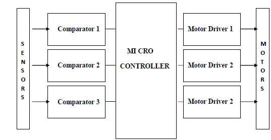
 The irrigation pump in the autonomous irrigation system is powered by solar energy. Monitoring the soil's water level and manually controlling the irrigation system get tiresome. As a result, instead of utilising conventional energy, the system generates solar power using photovoltaic cells. An op-amp IC that serves as a comparator and measures the soil moisture level is necessary for the project. Two copper wires are placed into the soil at a certain depth to gauge the soil's moisture content. The sensors provide data to the microcontroller, which interfaces with the relay driver IC to activate the relay and cause the pump motor to turn ON or OFF. An LCD screen displays the pump status.


IOT Car Parking System

 In today's contemporary, crowded cities, parking is a huge problem. There are just too many cars on the road and not enough places to park them. Effective parking management solutions are now required as a result of this. Therefore, we show how to implement an IOT-based parking management system that enables effective parking spot usage. We utilise IR sensors to detect parking space occupancy and DC motors to represent gate opening motors in order to illustrate the idea. We now operate the system using an AVR microcontroller and a wifi modem for internet access. For internet connection and IOT administration GUI design, we utilise IOTGecko. Using IR sensors, the system determines if parking spaces are occupied. In order to open the gate automatically, it also employs IR technology to detect the presence of a vehicle at the entrance. To enable online parking slot availability checks, the system scans the number of parking spaces that are available and updates data with the cloud server. This enables customers to find hassle-free parking by checking the availability of parking spots online from any location. Thus, the system offers customers an effective IOT-based parking management solution while resolving the parking problem for cities.


Sunday, 22 June 2014

Pull Pin Security Alarm System

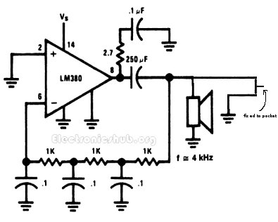
his circuit helps us to get alerted when anybody picks our pockets or bags. The circuit is very helpful to prevent our goods getting pick pocketed. The circuit is called a pull pin security alarm because it gets activated as soon as the pin is pulled.
The arrangement of the circuit is as follows. The circuit has a pin which is fixed to the pocket and the other end is attached to the circuit. The circuit remains inactive until the wallet is in your pocket as the circuit gets activated when the wallet is pulled from your pocket.
When the wallet is in the pocket, the circuit has the pin attached thereby the circuit remains inactive. Whereas when the wallet is removed from the pocket, the pin gets detached from the circuit thereby the circuit gets activated. When the circuit gets activated, the circuit turns ON the mini loudspeaker. The mini loudspeaker is fed with an alternating signal of audio frequency. This signal vibrates the loud speaker at an audio frequency so that it is well heard to us.

Wednesday, 6 June 2012

Digital Stethoscope

Overview

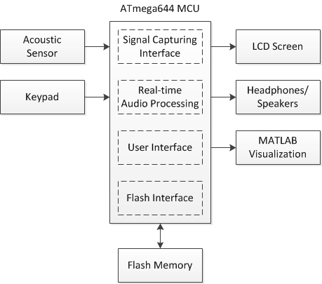
The overall architecture of the system is centered on the ATmega644 microcontroller. The acoustic sensor and keypad are inputs to the MCU, while the LCD, headphones, and MATLAB visualization tool are outputs. Communication with the Flash memory is bi-directional. Figure 2 shows an overview of the system high level design.


Figure 2. System High Level Design

The MCU runs several software interfaces to support the various features of the digital stethoscope. The signal capturing interface uses the analog-to-digital converter to sample the acoustic sensor at 8 kHz. The real-time audio processing module modifies the measured signal based on user settings and outputs it to the 3.5 mm audio socket via pulse-width modulation. The user interface supports the detection and de-bouncing of keypad button presses as well as controls the LCD display to reflect the current state of the system. In addition, the user interface also outputs real-time or recorded data at 100 Hz to a MATLAB utility running on a separate PC for signal visualization and average heart rate calculations. The Flash interface includes a software library for SPI communication to read from and write data to the external Flash memory chip.

Sunday, 6 May 2012

Gas Leak Detection

Abstract

The aim of the project is to develop a gas leak detection and location system for the production safety in Petrochemical Industry.

PURPOSE:

The purpose of the project is to monitor gas leakage parameter. When they exceeds threshold, intimation is given to the nearby control section including readings of parameter and location of the gas leakage.

Description:

The system is based on Wireless Sensor Networks (WSN) it can collect the data of monitoring sites wirelessly and sent to the computer to update values and the location also. Consequently, it can give a real time detective of the potential risk area, collect the data of a leak accident and locate the leakage point. However the former systems cannot react in time even cannot obtain data from an accident and locate accurately.

The paper has three parts, first, gives the overall system design, and then provides the approaches on both hardware and software to achieve it. The gas leak detection and location system consists of three parts: control center and terminal nodes.

Here the supervising control center is based on arm controller, it displays the location and the status messages of parameters of all the monitoring sites, and it is a graphical description of the geographical information of the entire potential risk area. Status, sensor data and location data, and then sent them to the control center to update value in the location software

TECHNOLOGY:

Zigbee is new wireless technology guided by IEEE 802.15.4 Personal Area Network standard. It is primarily designed for the wide range controlling applications and to replace the existing non-standard technologies. It currently operates in 868 MHz band at a data rate of 20Kbps in Europe, 914MHz band at 40kbps in USA, and the 2.4GHz ISM bands Worldwide at a maximum data-rate of 250kbps. It is used to verify whether user's truncation is possible or not. One of the main advantages of this ZIGBEE communication is that it provides a noise free communication, the amount of noise added in this type of communication is very less compared to the other wireless communications

RESULT:

Hence a gas leak detection and location system for the production safety in Petrochemical Industry was designed

Attendance Management Using Face Recognition System

The aim of this project is to deal with the problem of face detection in color images. Unlike in face recognition, where the classes to be discriminated are different faces in face detection, the two respective classes are the “Face area” and the “Non face area”. The novel approach to face detection is presented, binarisation rules especially designed for a skin area detection within a image frame.

The process involves Binarisation, localization, training and identification of Human Face.

This project easily extract the human face from any other images. Image segmentation algorithm is used to identify the face from other images.

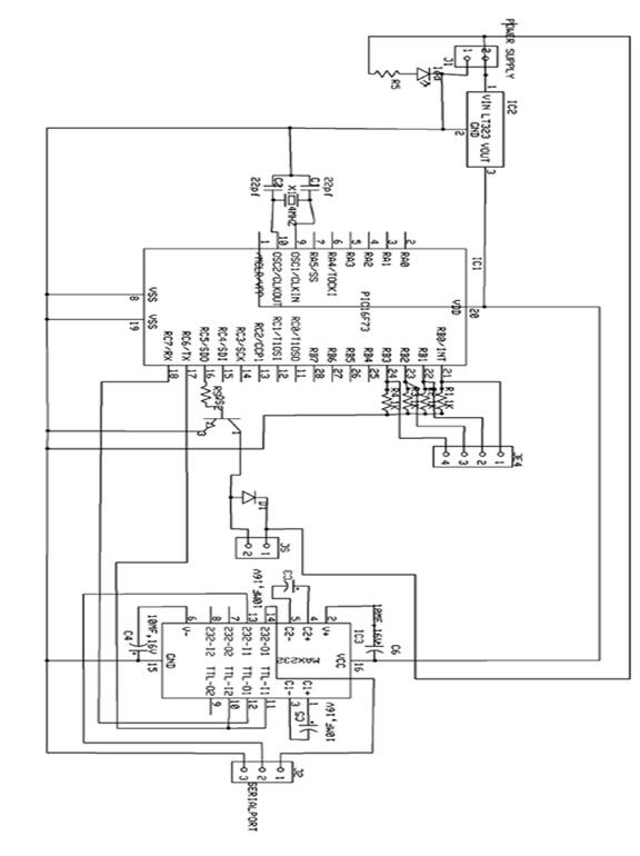
After recognizing the face, the PC puts the attendance for the particular user. Also it sends signal to the microcontroller through serial port. The microcontroller analyses the signal and operates the door motor through driver section. The microcontroller program is written in assembly language. The microcontroller used is PIC 16F73

In this project, the camera is replaced by CD drive. The face is stored in the CD. As soon as the particular CD is inserted, the software in the PC recognizes the face and sends signal to the microcontroller through serial port. The PC recognizes the face and checks the data with the existing data. If it matches with any data, it puts attendance for the particular user. Also it sends signal to the microcontroller

The microcontroller used in this circuit is PIC16F73. It is a 28 pin IC with three I/O ports. It has inbuilt ADC. According to the signal received from the camera, the values are stored in the RAM of the microcontroller. Accordingly the microcontroller controls the door motor through driver section and relay. The microcontroller program is written in assembly language. The assembly language program is compiled to form “hex” code. The “hex” code is written in the microcontroller using PIC write software with the help of PIC writer.

Bluetooth Energy Meter

Abstract

The word automation brings to mind devices that operate with minimal human intervention. In other words, acting or operating in a manner essentially independent of external influence or control. It finds application in controlling industrial equipments, home appliances, computer peripherals and robots. Bluetooth is a promising new wireless technology, which enables portable devices to form short-range wireless ad hoc networks and is based on a frequency hopping physical layer. Bluetooth is a frequency hopping system, which defines multiple channels for communication (each channel defined by a different frequency hopping sequence). A group of devices sharing a common channel is called a piconet. Each piconet has a master unit, which selects a frequency hopping sequence for the piconet and controls the access to the channel. Other participants of the group known as slave units are synchronized to the hopping sequence of the piconet master

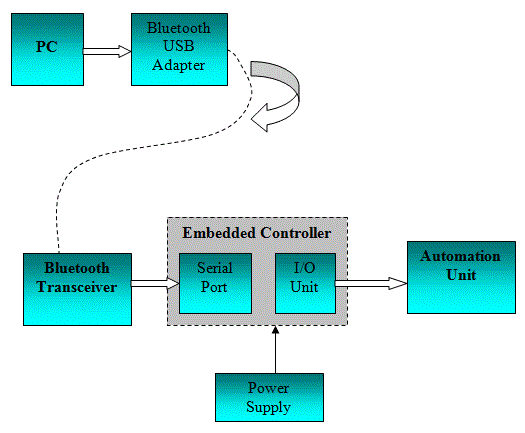
Home and office automation using Bluetooth enabled devices have generated sufficient interest in the networking community. Bluetooth based automation offers flexibility, even when the devices actually present far from the master unit. The commands for the automation unit are given through the software module in PC. From PC the command is given to Bluetooth USB adapter. The Bluetooth USB adapter enables the Bluetooth communication and converts the data into airborne signals. The Bluetooth transceiver has a built-in antenna receives the air borne signals and transfer the data to the embedded controller through serial port. The Bluetooth transceivers can be operated in point-to-point, point-to-multipoint and multipoint-to-multipoint architectures.

The embedded microcontroller is programmed to read the data. The embedded controller is the CPU that decides the operation of the automation unit. The embedded controller used here is 89C51 microcontroller. It is a derivative of 8051 microcontroller whose architecture and instruction set are same as 8051 microcontroller with some additional functionality. Since the controller has the inbuilt peripherals it is called as embedded controller. The embedded controller controls the automation unit as per the commands. Bluetooth based systems are developed to manage proper safeguards to prevent unauthorized leakage of information. Synchronizing data between cell phones, laptops, and PDAs; using cell phones as cordless phones when at home; and connecting PDAs to the office LAN are some of the cumbersome things that are possible with Bluetooth

Design of a Wireless Medical Monitoring System

Design of a Wireless Medical Monitoring System

Abstract

The main aim of this project is used Monitoring Terminal and it can detect the patient's real-time body temperature, heart rate and other physiological informations, and transmit them to the control center.

PURPOSE :

Now days the fast development and popularization of information processing and wireless data transmission technology, the research of wireless Medical Monitoring System has became a hot topic with the help of biomedical sensors. By utilizing the wireless technique to transmit information between medical sensor and monitoring control center, the free space of patients is enlarged, and the efficiency of the modern management of hospitals is improved

DESCRIPTION:

Now a day with the increase of biomedical sensor we are going into this process of detecting the patient's real-time body temperature, heart rate and other physiological information's .Coming to the main core of wireless medical monitoring system is the design of wireless monitoring terminal, and the development of system software. The monitoring terminal generally consists of three modules: the sensor module, the control module, and the wireless communication module. The sensor module is used for acquiring medical information from the outside, and then converts them to digital signals. The control module is often compared to the brain of monitoring terminal, which is in charge of coordinating the task of different modules, controlling the sensors, processing data, and executing communication protocols.

The wireless communication module mainly deals with the wireless transmission of information. Nowadays, there are various kinds of wireless communication protocols. But since the main task of a monitoring terminal is to realize the transmission of signals such as heart rate, body temperature, and calling signals the data traffic is not heavy. Moreover, because the monitoring terminal is worn on patients, which needs to be supplied by battery, it puts a high demand on the reducing of power dissipation of wireless transmission module. Having taken these comprehensive factors into consideration, this paper chooses the ZigBee technology as the wireless communication protocol. ZigBee technology is a shortrange, low-rate, low-power wireless communication technology

TECHNOLOGY:

Zigbee is new wireless technology guided by IEEE 802.15.4 Personal Area Network standard. It is primarily designed for the wide range controlling applications and to replace the existing non-standard technologies. It currently operates in 868 MHz band at a data rate of 20Kbps in Europe, 914MHz band at 40kbps in USA, and the 2.4GHz ISM bands Worldwide at a maximum data-rate of 250kbps. It is used to verify whether user's truncation is possible or not. One of the main advantages of this ZIGBEE communication is that it provides a noise free communication, the amount of noise added in this type of communication is very less compared to the other wireless communications

Hence, by implementing this project the monitoring terminal can precisely check the heart rate and body temperature of patients, and send them to coordinator and then surveillance center through wireless network.

Solar Based Electromagnetic Braking System

The objective of this project is to design the solar based Electromagnetic breaking system using Object sensor for Automobiles. This project is mainly used in Vehicles either two or four wheelers. In this project is used in real time we can avoid so many accidents.

Brief Methodology:

This project is designed by following blocks

• Microcontroller

• Solar panel with battery.

• Object sensor

• Driver circuit

• Relay

• Electromagnetic core

• Breaking system

The object sensor senses the object and gives corresponding signals. These electrical signals are very small mill voltage signal, so it is given to amplifier circuit. The amplifier circuit is constructed with operational amplifier which acts as power amplifier. Then the amplifier signal is given to signal conditioning unit which also constructed with operational amplifier. In this circuit operational amplifier act as comparator and generate the square pulse given to microcontroller. The microcontroller may be ATMEL/PIC/RENESAS/ARM microcontroller. It will work according to our object already we have programmed.

According to the object sensor value, the microcontroller activates the driver circuit as per mentioned in the program. The driver circuit is constructed with transistor which acts as switch to control the relay. The relay output is directly connected to the electromagnetic core which is attached in the breaking system.

Whenever we control the brake, at the time what happens in the system means one of the coil winding is placed around it. It generates the electromotive force and it's fitted with the suitable mechanical set. Likewise when we release the break the force generation will be stopped and the coil winding releases from the mechanical set.

Entire kit is controlled by only solar power. Solar panel consists of number of silicon cells, when sun light falls on this panel it generate the voltage signals then these voltage signals given to charging circuit. Depends on the panel board size the generated voltage amount is increased. In charging circuit the voltage signal from the board is gathered together and stored in the battery. The battery power is used to control the vehicle

Advantage:

  • Can use all type of vehicles
  • Low cost
  • Low power consumption

Body Motion Information Collection

Abstract

This project is utilizes multiple- Knot network technology to gather multiple –point accelerations information's.

PURPOSE:

This paper deals with the Numerous experiment data indicate it gather accurate information about human body which reflect the truthfully human body motions and this paper is process or transmit it to advanced comprehensively analyzed and this is widely used in such fields are health recovery training, physical exercises, computer games controlling. And here some mathematical calculations about the acceleration component information such as motional track and dynamic process will be gotten for this platform

Description:

Any human body motion, from its beginning to the end, the acceleration of every part of the mobile limbs or other parts of human body is keeping changing. If certain motion is repeated, then its acceleration changing regularity is also very also very close. Therefore if a three-axis acceleration sensor is put on some typical point of measured limbs or other body parts, then the three acceleration components X_Y_Z of that typical point in the motion process can be collected accurately.

Then by mathematical calculation about the acceleration components information such as the motional track and dynamic process about that point will be gotten.

From comprehensive analysis of the data gathered about several typical points detailed information about the measured human body motions is obtained so that motion information is digitalized.

This motion information collection platform uses multi-knot internet technology to

Collect the acceleration information of multiple typical points simultaneously, and process or transmit it to advanced computers to be comprehensively analyzed, thus this platform can be widely used in such fields as health recovery training, physical exercises, computer games controlling

TECHNOLOGY:

Micro-Electro-Mechanical Systems (MEMS) is the integration of mechanical elements, sensors, actuators, and electronics on a common silicon substrate through microfabrication technology. While the electronics are fabricated using integrated circuit (IC) process sequences (e.g., CMOS, Bipolar, or BICMOS processes), the micromechanical components are fabricated using compatible "micromachining" processes that selectively etch away parts of the silicon wafer or add new structural layers to form the mechanical and electromechanical devices.

MEMS promises to revolutionize nearly every product category by bringing together silicon-based microelectronics with micromachining technology, making possible the realization of complete systems-on-a-chip . MEMS is an enabling technology allowing the development of smart products, augmenting the computational ability of microelectronics with the perception and control capabilities of micro sensors and micro actuators and expanding the space of possible designs and applications

RESULT:

By this controller we get the information according to motion of the body.

SMS Controlled Industrial Controller

In a process control industry, it is very difficult for a person to be present or to monitors the system continuously. If not, there occurs damage in the whole process industry. In order to view the process continuously and to check the status of the process we are going to use our project “SMS CONTROLLED INDUSTRIAL CONTROLLER”. This project has been implemented in various platforms, now we are going to do this project using LABVIEW Here we can monitor any number of process parameters. The hardware unit consists of all the hardware requirements needed for the process.

This project is implemented by using LABVIEW software to send the message when there prevails any deviation in the process station. Suppose to say, if we are monitoring eight parameters we have to set the limits for all the parameters so that if any parameter value goes out of range then the corresponding message will be sent to the operator indicating there is a deviation in the process.

The parameters like temperature, voltage, speed, current, level, pressure etc. can be measured by using the LABVIEW software. The hardware unit is interfaced with the system using LPT terminal to PC. In our program we have to enable the parallel port mode by setting the appropriate register values to the port. By using ADC configuration using the program, data acquisitions from different channels are performed. Plotting the graphs for these values with respect to time.

If the parameter value goes out of range, then the message is sent to the operator. One mobile is connected to the PC that is having the hardware interface unit and the other one will be with the operator. To send the message to the other user, we have to do the following settings. First of all we have to establish serial communication using VISA card. After setting the serial communication mode, enter the phone number and the message that has to be sent. This will indicate only if there is any deviation in the parameter value. We can also use buzzer to get ON whenever the data's acquired goes out of range by using DIGITAL OUTPUT configuration using the LABVIEW program.

For this we have to out the data as 1 or 0 to ON and OFF the buzzer unit for indication purpose. The hardware unit is interfaced with the PC by accessing the parallel port and the mobile phone is connected with the PC by accessing the serial port. The Speed parameter can be measured and controlled by using DAC configuration in lab view. Initially set the motor speed at a particular rpm by using the above said mode by counting the data from 00 to FF. By using DIGITAL INPUT configuration, count the number of pulses for every five seconds and convert it into rpm. Compare the current speed with the set speed and out the data using DAC configuration and monitor the speed value in the PC through LPT terminal. If the parameter value goes out of range, then the message is sent to the operator

APPLICATION:-

• This project is very useful in the industrial application

Sunday, 29 April 2012

Railway Switches And Signals

Signals, including those used for communication between occupants of a car or train.Indicators, recorders, telegraphic, telephonic, or other similar apparatus when especially designed for use in connection with car or train movements, except manually-set devices, such as train and engine signs and markers capable of general use.

Devices on the roadway, such as signals, switches, circuit closures, gates, etc., actuated or controlled from or by the moving vehicles, except circuit-controllers actuated by the vehicle for the purpose of energizing sectionalized conductors used for supplying propulsion-current thereto.

Automatic train stop and speed control means, the actuation of which is initiated by agencies not on the train or by wheel derailment or defects in train structure and mechanism, the automatic stop, for classification purposes, being considered an equivalent of and substitute for a railway signal; but train stopping and control mechanism cooperating with obstacles fixed in position upon the track which have no moving parts are excluded from this class except when they cooperate with speed-responsive devices on the train.

Safety devices, including derailing switches and blocks, used for preventing accidents caused by the misplacement of switches, disregard of signals etc.The structure of signals, switches, frogs, and crossings and their appurtenances.Mechanism for the manual or other actuation of any of the devices of the class.

Remote Vehicle With Unlimited Range

In this project, the robot is controlled by the mobile phone that makes a call to the mobile phone attached to the robot .In the course of a call, if any button is pressed; a tone corresponding to the button pressed is heared at the other end of the call. This tone is called ‘dual tone-multiple-frequency' (DTMF) tone .The robot perceives the DTMF tone with the help of the phone stacked in the robot.

The received tone is processed by the ATmega16 microcontroller with the help of DTMF decoder MT8870.The decoder decodes the DTMF tone into its equivalent binary digit and this binary number is sent to the microcontroller. The microcontroller is programmed to take a decision for any given input and outputs its decision to motor drivers in order to drive the motor for forward or backward motion or a turn.

The mobile that makes a call to the mobile stacked in the robot as a remote. So this simple robotic project does not require the construction of receiver and transmitter units. DTMF signaling is used for telephone signaling over the line in voice-frequency band to the call switching center. The version of DTMF used for telephone tone dialing is known as ‘Touch Tone'. DTMF assigns a specific frequency (consisting of two separate tones) to each key so that it can easily be identified by the electronics circuit. The signal generated by the DTMF encoder is a direct algebraic summation, in real time, of the amplitude of two sine (cosine) waves of different frequency, i.e., pressing ‘5' will send a tone made by adding 1336Hz and 770Hz to the other end of end of the line .The tones and assignment in a DTMF system are shown in table I.

CIRCUIT DESCRIPTION:

The important components of this rover are a DTMF decoder, microcontroller and motor driver. An MT8870 series DTMF decoder is used here. All types of the MT8870 series use digital counting techniques to detect and decode all the 16DTMF tone pairs into 4-bit code output. The built in dial tone rejection circuit eliminates the need for pre-filtering. When the input signal given at pin 2(IN-) in single-ended input configuration is recognised to be effective, the correct 4-bit decode signal of the DTMF tone is transferred to Q1 (PIN11) through Q4 (PIN14) outputs.

The ATmega16 is a low power ,8-bit ,CMOS microcontroller based on AVR enhanced RISC architecture .It provides the following features:16kb of in-system programmable flash program memory with read-while-write capabilities ,512 bytes of EEPROM ,1kb SRAM,32 general purpose I/O lines and 32 general purpose working registers. All the 32 registers are directly connected to arithmetic logic unit ,allowing two independent register to be accessed in one single instruction executed in one clock cycle .The resulting architecture is more code-efficient.

Output from port pins PD0 through PD3 and PD7 of the microcontroller are fed to inputs IN1 through UN4 and enable pins (EN1 and EN2) of motor driver L293D, respectively, to drive two geared dc motor. Switch S1 is used for manual reset. The microcontroller output is not sufficient to drive the DC motors, so current driver are required for motor rotation.

The land rover can be further improved to serve specific purpose .It require four controls to roam around .The remaining eight controls can be configured to serve other purposes, with some modification in the source program of the microcontroller.

Automated Step Climber

Human body is perfect combination of motion, balance, co-ordination and reflex. It because human brain is so much developed that all these activities can take place in such perfect co-ordination. With advancement in science we humans have created many beautiful creations and robot happens to be one of them. Humans have developed robots that can mimic humans. In the same context it is our humble effort to develop an electro-mechanical autonomous robotic vehicle that can have multiple degree of freedom, which enable it to move through various terrains.

Taking inspiration from NASA’s path finder robot we have tried to make a tone down prototype which control its movement with help of microcontroller which properly co-ordinate its motion. In our project we have tried to built an electro-mechanical autonomous robotic vehicle, which moves over the hurdles in front of it by sensing obstacle with help of sensing circuit and taking controlled action with microcontroller ,which drives the motors to make robot climb over the obstruction.

We have used many other chips to achieve this motion which we have described in the component section. This robotic vehicle could become a prototype for surveillance vehicle and other military vehicles used for detection and detonation of mines .Since cost of this prototype is very less thus it could be inducted in army easily and be made indigenously.Mainly ou project is based on working of microcontroller for the automatic management and motors for hardware management.

At initial position all the wheels are on the ground and microcontroller is programmed in such a way that the robo moves forward till the sensor circuit detect any obstruction. The sensor circuit consist of IR LED and phototransistor .The IR LED emits the IR radiations ,when there no obstruction the phototransistor does not detect any reflected radiation and the vehicle moves forward without any vertical motion.

When any obstruction comes in front of sensor mounted in front of wheel one the IR radiation are reflected back from the obstruction which is picked up by phototransistor .This phototransistor supplies a trigger signal to the comparator which conditions the signal and supplies the signal to microcontroller. The forward motion of the robo stops and microcontroller then detect the signal on a programmed pin. According to programming controller send the signal to the motor driver .

The motor driver drives the rack and pinion which lifts the wheel set one from the ground. The phototransistor detect the radiated IR radiations till the IR LED moves above the obstacle. As the wheels thus IR LED moves above the obstruction no sensor detect any signal thus forward motion of robo is initiated by the controller. Now the second detector detect the obstruction and same action is repeated as in case of first sensor. Once the second wheel moves over the obstruction the center of gravity moves in such a position that robo cannot topple. Thus in similar way third and last wheel climb over the obstruction and the robo moves above the obstruction.


Monday, 9 April 2012

Heat Control System

Introduction

This project was the first stage of developing a controller for a radiant floor heat system. The microcontroller will use inputs from thermostats, thermocouples, a flow meter, and pressure switches to control the operation of the pumps and valves to achieve improved efficiency of the system as a whole.

This project idea came from a friend who recently built a house which utilizes an outdoor wood boiler for heating. He expressed that he was disappointed in the efficiency of the current system and wished he had more control over the system operation. This seemed like a good application of what I�ve learned in this course. The main goal is to improve the efficiency of the system by shortening the amount of time that the Pumps need to run while still properly heating the home. By doing this, consumption of both electricity and wood will be reduced.

Implementation of this project involves a large amount of work outside of the microprocessor. Because of this, I bound the scope of this academic project to the control logic only. In order to implement this in the house, I will have to build the circuitry to translate the control logic over to the voltages necessary for operation of the valves, pumps and sensors. In order to verify and validate the controller logic worked as desired I built a demonstration board that models the inputs and outputs of the system. This board was used to debug the controls during development and it was also a convenient way of demonstrating this project at the end of the semester. Toggle switches were used to model the 5 thermostats, adjustable voltage dividers were used for thermocouples, a 555 Timer circuit was used for the flow meter and LEDs were used for all outputs.

Thursday, 12 January 2012

Engineering Project Ideas

A Simple Control Scheme for Single-Phase Shunt Active Power with Fuzzy Logic based DC Bus Voltage Controller

2009Space Vector Pulse Width Modulation based Speed Control of Induction Motor usingFuzzy PI Controller

2009Energy Efficient Control of Three-Phase Induction Motor

A Review

2009Speed-Sensorless, Adjustable-Speed Induction Motor Drive based on Dc Link Measurement

2009A Bridgeless PFC Boost Rectifier with Optimized Magnetic Utilization

2009A Review of Non-Isolated High Step-Up DC/DC Converters in Renewable Energy Applications

2009An Interleaved Twin-Buck Converter with Zero-Voltage-Transition - 2009Analysis and design of a current-fed zero-voltage-switching and zero-current-switching CL-resonant push

pull dc

dc converter - 2009Analysis and implementation of An Efficient ActiveL C Snubber for Forward Converters - 2009Analysis and implementation of positive output super lift converter techniques -2009Digital Control of Resonant Converters: Enhancing Frequency Resolution by Dithering

2009Semi-Digital Interleaved PFC Control with Optimized Light Load Efficiency

2009Control and Protection of Power Electronics Interfaced Distributed Generation Systems in a Customer-Driven Microgrid

2009Research on Measuring Equipment of Single-phase Electricity-Stealing with Long-distance Monitoring Function

2009Development of Energy Management and Warning System for Resident: An Energy Saving Solution

2009Sufficient Sunlight Supply for Home Care using Local Closed-loop Shutter ControlSystem

2009Home Appliance Energy Monitoring and Controlling based on Power Line Communication - 2009Comprehensive Approach to Modeling and Simulation of Photovoltaic Arrays - 2009A Novel Zero Voltage Transition Synchronous Buck Converter for Portable Application

2008Detection and Recognition of End-of-Speed-Limit and Supplementary Signs for Improved European Speed Limit Support

2008Soft Switched AC-Link AC/AC and AC/DC Buck-Boost Converter

2008Improving Speed Control of Induction Motors through Fuzzy-SMC-PI Control
A Fuzzy Logic Controlled Sliding Mode Control (SMC) of Inverter in Shunt ActivePower Filter for Power Quality Improvement

2008Design of an Intelligent Bi-Directional DC-DC Converter with Half Bridge Topology

2008Direct Torque Neuro Fuzzy Speed Control of an Induction Machine Drive based on aNew Variable Gain PI Controller

2008Embedded Controlled Z Source Inverter Fed Induction Motor Drive

2008Multi-Input Fuzzy Logic Controller for Brushless DC Motor Drives

2008Smart Configurable Wireless Sensors and Actuators for Industrial Monitoring andControl

2008Design and Implementation of PLC-based Monitoring Control System for Three-PhaseInduction Motors Fed by PWM Inverter

2008A Distributed Measurement System to Estimate Plant Water Content in AgriculturalFields based on Wireless Sensor Networks

2008Operational Analysis and Comparative Evaluation of Embedded Z-Source Inverters

2008AI base Design of a Fuzzy Logic Scheme for Speed Control of Induction Motors using SVPWM Technique

IEEE 2009CAN-based Synchronized Motion Control for Induction Motors

IEEE 2009Fuzzy Multi-State Allocation of the Diesel Engine Fuel Supply System

IEEE 2009A Fuzzy Logic based Supervisory Hierarchical Control Scheme for Real Time Pressure Control

IEEE 2009A Fuzzy Logic Controlled Sliding Mode Control (SMC) of Inverter in Shunt ActivePower Filter for Power Quality Improvement

IEEE 2008A Novel Zero Voltage Transition Synchronous Buck Converter for Portable Application

IEEE 2008Design of an Intelligent Bi-Directional Dc-Dc Converter with Half Bridge Topology

IEEE 2008Direct Torque Neuro Fuzzy Speed Control of an Induction Machine Drive based on aNew Variable Gain PI Controller

IEEE 2008Embedded Controlled Z-Source Inverter Induction Motor Drive

IEEE 2008Improving Speed Control of Inductions through Fuzzy-SMC-PI Control

IEEE 2008Multi-Input Fuzzy Logic Controller for Brush less DC Motor Drives

IEEE 2008A New Simplified Multilevel Inverter Topology for DC-AC ConversionBoost DC-AC Inverter: A New Control StrategyData Acquisition System for Large Electrical Drive

Distribution & Electrical Substation System & Automation-SCADA

Electrical Network Automation & Communication Systems

Energy Saver for Auditoriums

Electronic Numeric Key Board cum Motorized (Mechanism) Safety Locker System withElectronic Security System

IGBT based PWM Inverter using MicrocontrollerEnergy Saving using Thyristorized Power Converters

Multiple Starters with Over Load and Low High Voltage Protection

Fault Tolerant Neuro Controlled Level Processing Panel

Energy Saving in Single Phase Induction Motor using A.C Chopper

Fuzzy Logic based Faults Identification System for a Three- Phase Induction Motor

Intelligent Power Sharing of Transformers with Auto Protection

Measurement of the Radio Frequency Signal of a Circuit-Breaker

Microcontroller based Measurement of Current, Voltage, Power Factor and Temperature

Multichannel Petrochemical Fire Sensor, Monitoring and Control System with Automatic Telephone Dialing

Neural Implementation of Energy Consumption In Power Distribution

Neural Implementation of Fault Diagnosis of TransformersPower Line Fault Analysis, Monitoring and Load Sharing System

Programmable Temperature Control System

Remote Access Control and Automation System for Electrical Appliances using Telephone LineRemote Data Monitoring & Data Analysis for Power Station

RF based Intelligent Handheld Multi-Parameter Monitoring System with LCD Display

and DASSoft Starter and Energy Saver for 1-Phase Induction Motor using Bi-directional Voltage Regulator

Fuzzy Logic based Speed Control of AC Motor using Microcontroller with Line Fault
Identification

Thermal Overload Protection for TransformerCycloconverter Drive for AC MotorsDigital PID Controller Based Speed Control of DC Motor

Friday, 2 December 2011

Micro Controller based Security System using Sonar

The problem facing many institutions like museums and banks is that of security round the clock. Security guards are expensive and burglars have learned to evade conventional security devices like infrared beams, thermal sensors etc. The use of SONAR in a security system, as used in our project, is a novel idea, and as far as we could determine, extremely difficult, if not impossible, to evade. The infrared beams have the disadvantages of covering just a limited area in a room
and to cover a whole room requires many of these beams. This makes this technology very expensive. It is also by no means foolproof and can be evaded by experts as has been so ably demonstrated in so many Hollywood films. Temperature sensors can also be evaded as they can either be made extremely sensitive and risk false tripping of the alarm due to changes in ambient temperature or made less sensitive at the risk of allowing evasion. The use of SONAR offers us many advantages. It is nearly foolproof, albeit it be at the expense of being extremely sensitive to the point that the only way to avoid tripping of the alarm is to make sure that the room it is covering is free from any movements. In this project we have designed and developed a unique security system that utilises the capabilities of microcontroller and a special purpose SONAR
module. It is also extremely cost-effective when compared to similar systems currently in use.

LED-Following Car

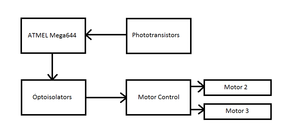
hardware logic structure looks as follows:

High level design
In our project, the phototransistors sent their outputs to the ATMEL Mega644 microcontroller. The MCU then calculates which motors should move based on the phototransistors and sends a signal to the optoisolators telling which motors to turn on. Depending on which optoisolator is turned on, the motor control will tell which motor to move. We used optoisolators to separate the MCU from the motor circuitry. Optoisolators isolate the LED side of the circuit from the phototransistor side of the circuit, ideally protecting the MCU from any unknown outputs from the motor controller.

Saturday, 19 November 2011

maximum power point tracker (or MPPT)

A maximum power point tracker (or MPPT) is a high efficiency DC to DC converter which functions as an optimal electrical load for a photovoltaic (PV) cell, most commonly for a solar panel or array, and converts the power to a voltage or current level which is more suitable to whatever load the system is designed to drive. PV cells have a single operating point where the values of the current (I) and Voltage (V) of the cell result in a maximum power output. These values correspond to a particular resistance, which is equal to V/I as specified by Ohm's Law. A PV cell has an exponential relationship between current and voltage, and the maximum power point (MPP) occurs at the knee of the curve, where the resistance is equal to the negative of the differential resistance (V/I = -dV/dI). Maximum power point trackers utilize some type of control circuit or logic to search for this point and thus to allow the converter circuit to extract the maximum power available from a cell. Traditional Solar Inverters perform MPPT for an entire array as a whole. In such systems the same current, dictated by the inverter, flows though all panels in the string. But because different panels have different IV curves, i.e. different MPPs (due to manufacturing tolerance, partial shading, etc.) this architecture means some panels will be performing below their MPP, resulting in the loss of energy.
The Power point tracker is a high frequency DC to DC converter. They take the DC input from the solar panels, change it to high frequency AC, and convert it back down to a different DC voltage and current to exactly match the panels to the batteries. MPPT's operate at very high audio frequencies, usually in the 20-80 kHz range. The advantage of high frequency circuits is that they can be designed with very high efficiency transformers and small components. The design of high frequency circuits can be very tricky because the problems with portions of the circuit "broadcasting" just like a radio transmitter and causing radio and TV interference. Noise isolation and suppression becomes very important. There are a few non-digital (that is, linear) MPPT's charge controls around. These are much easier and cheaper to build and design than the digital ones. They do improve efficiency somewhat, but overall the efficiency can vary a lot - and we have seen a few lose their "tracking point" and actually get worse. That can happen occasionally if a cloud passed over the panel - the linear circuit searches for the next best point, but then gets too far out on the deep end to find it again when the sun comes out. Thankfully, not many of these around any more. The power point tracker (and all DC to DC converters) operates by taking the DC input current, changing it to AC, running through a transformer (usually a toroid, a doughnut looking transformer), and then rectifying it back to DC, followed by the output regulator. In most DC to DC converters, this is strictly an electronic process - no real smarts are involved except for some regulation of the output voltage. Charge controllers for solar panels need a lot more smarts as light and temperature conditions vary continuously all day long, and battery voltage changes.