
Overview
The overall architecture of the system is centered on the ATmega644 microcontroller. The acoustic sensor and keypad are inputs to the MCU, while the LCD, headphones, and MATLAB visualization tool are outputs. Communication with the Flash memory is bi-directional. Figure 2 shows an overview of the system high level design.
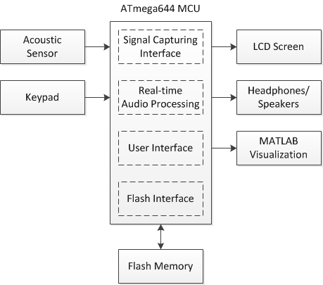
Figure 2. System High Level Design
The MCU runs several software interfaces to support the various features of the digital stethoscope. The signal capturing interface uses the analog-to-digital converter to sample the acoustic sensor at 8 kHz. The real-time audio processing module modifies the measured signal based on user settings and outputs it to the 3.5 mm audio socket via pulse-width modulation. The user interface supports the detection and de-bouncing of keypad button presses as well as controls the LCD display to reflect the current state of the system. In addition, the user interface also outputs real-time or recorded data at 100 Hz to a MATLAB utility running on a separate PC for signal visualization and average heart rate calculations. The Flash interface includes a software library for SPI communication to read from and write data to the external Flash memory chip.


0 comments:
Post a Comment