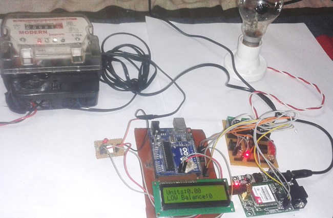
e conventional energy meter reading system may cause low accuracy and low efficiency. This project, energy meter reading over internet facilitates the display of units consumed and cost over the internet (in the form of chart and gauge).

Abstract
The aim of the project is to develop a gas leak detection and location system for the production safety in Petrochemical Industry.
PURPOSE:
The purpose of the project is to monitor gas leakage parameter. When they exceeds threshold, intimation is given to the nearby control section including readings of parameter and location of the gas leakage.
Description:
The system is based on Wireless Sensor Networks (WSN) it can collect the data of monitoring sites wirelessly and sent to the computer to update values and the location also. Consequently, it can give a real time detective of the potential risk area, collect the data of a leak accident and locate the leakage point. However the former systems cannot react in time even cannot obtain data from an accident and locate accurately.
The paper has three parts, first, gives the overall system design, and then provides the approaches on both hardware and software to achieve it. The gas leak detection and location system consists of three parts: control center and terminal nodes.
Here the supervising control center is based on arm controller, it displays the location and the status messages of parameters of all the monitoring sites, and it is a graphical description of the geographical information of the entire potential risk area. Status, sensor data and location data, and then sent them to the control center to update value in the location software
TECHNOLOGY:
Zigbee is new wireless technology guided by IEEE 802.15.4 Personal Area Network standard. It is primarily designed for the wide range controlling applications and to replace the existing non-standard technologies. It currently operates in 868 MHz band at a data rate of 20Kbps in Europe, 914MHz band at 40kbps in USA, and the 2.4GHz ISM bands Worldwide at a maximum data-rate of 250kbps. It is used to verify whether user's truncation is possible or not. One of the main advantages of this ZIGBEE communication is that it provides a noise free communication, the amount of noise added in this type of communication is very less compared to the other wireless communications
RESULT:
Hence a gas leak detection and location system for the production safety in Petrochemical Industry was designedThe aim of this project is to deal with the problem of face detection in color images. Unlike in face recognition, where the classes to be discriminated are different faces in face detection, the two respective classes are the “Face area” and the “Non face area”. The novel approach to face detection is presented, binarisation rules especially designed for a skin area detection within a image frame.
The process involves Binarisation, localization, training and identification of Human Face.
This project easily extract the human face from any other images. Image segmentation algorithm is used to identify the face from other images.
After recognizing the face, the PC puts the attendance for the particular user. Also it sends signal to the microcontroller through serial port. The microcontroller analyses the signal and operates the door motor through driver section. The microcontroller program is written in assembly language. The microcontroller used is PIC 16F73
In this project, the camera is replaced by CD drive. The face is stored in the CD. As soon as the particular CD is inserted, the software in the PC recognizes the face and sends signal to the microcontroller through serial port. The PC recognizes the face and checks the data with the existing data. If it matches with any data, it puts attendance for the particular user. Also it sends signal to the microcontroller
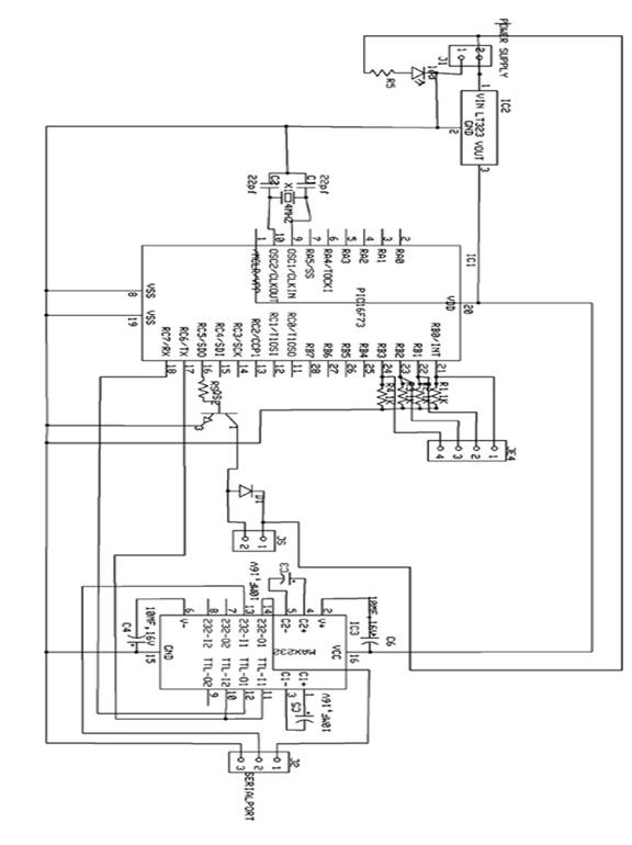
The microcontroller used in this circuit is PIC16F73. It is a 28 pin IC with three I/O ports. It has inbuilt ADC. According to the signal received from the camera, the values are stored in the RAM of the microcontroller. Accordingly the microcontroller controls the door motor through driver section and relay. The microcontroller program is written in assembly language. The assembly language program is compiled to form “hex” code. The “hex” code is written in the microcontroller using PIC write software with the help of PIC writer.
Abstract
The word automation brings to mind devices that operate with minimal human intervention. In other words, acting or operating in a manner essentially independent of external influence or control. It finds application in controlling industrial equipments, home appliances, computer peripherals and robots. Bluetooth is a promising new wireless technology, which enables portable devices to form short-range wireless ad hoc networks and is based on a frequency hopping physical layer. Bluetooth is a frequency hopping system, which defines multiple channels for communication (each channel defined by a different frequency hopping sequence). A group of devices sharing a common channel is called a piconet. Each piconet has a master unit, which selects a frequency hopping sequence for the piconet and controls the access to the channel. Other participants of the group known as slave units are synchronized to the hopping sequence of the piconet master
Home and office automation using Bluetooth enabled devices have generated sufficient interest in the networking community. Bluetooth based automation offers flexibility, even when the devices actually present far from the master unit. The commands for the automation unit are given through the software module in PC. From PC the command is given to Bluetooth USB adapter. The Bluetooth USB adapter enables the Bluetooth communication and converts the data into airborne signals. The Bluetooth transceiver has a built-in antenna receives the air borne signals and transfer the data to the embedded controller through serial port. The Bluetooth transceivers can be operated in point-to-point, point-to-multipoint and multipoint-to-multipoint architectures.
The embedded microcontroller is programmed to read the data. The embedded controller is the CPU that decides the operation of the automation unit. The embedded controller used here is 89C51 microcontroller. It is a derivative of 8051 microcontroller whose architecture and instruction set are same as 8051 microcontroller with some additional functionality. Since the controller has the inbuilt peripherals it is called as embedded controller. The embedded controller controls the automation unit as per the commands. Bluetooth based systems are developed to manage proper safeguards to prevent unauthorized leakage of information. Synchronizing data between cell phones, laptops, and PDAs; using cell phones as cordless phones when at home; and connecting PDAs to the office LAN are some of the cumbersome things that are possible with Bluetooth
Abstract
The main aim of this project is used Monitoring Terminal and it can detect the patient's real-time body temperature, heart rate and other physiological informations, and transmit them to the control center.
PURPOSE :
DESCRIPTION:
Now a day with the increase of biomedical sensor we are going into this process of detecting the patient's real-time body temperature, heart rate and other physiological information's .Coming to the main core of wireless medical monitoring system is the design of wireless monitoring terminal, and the development of system software. The monitoring terminal generally consists of three modules: the sensor module, the control module, and the wireless communication module. The sensor module is used for acquiring medical information from the outside, and then converts them to digital signals. The control module is often compared to the brain of monitoring terminal, which is in charge of coordinating the task of different modules, controlling the sensors, processing data, and executing communication protocols.
The wireless communication module mainly deals with the wireless transmission of information. Nowadays, there are various kinds of wireless communication protocols. But since the main task of a monitoring terminal is to realize the transmission of signals such as heart rate, body temperature, and calling signals the data traffic is not heavy. Moreover, because the monitoring terminal is worn on patients, which needs to be supplied by battery, it puts a high demand on the reducing of power dissipation of wireless transmission module. Having taken these comprehensive factors into consideration, this paper chooses the ZigBee technology as the wireless communication protocol. ZigBee technology is a shortrange, low-rate, low-power wireless communication technology
TECHNOLOGY:
Zigbee is new wireless technology guided by IEEE 802.15.4 Personal Area Network standard. It is primarily designed for the wide range controlling applications and to replace the existing non-standard technologies. It currently operates in 868 MHz band at a data rate of 20Kbps in Europe, 914MHz band at 40kbps in USA, and the 2.4GHz ISM bands Worldwide at a maximum data-rate of 250kbps. It is used to verify whether user's truncation is possible or not. One of the main advantages of this ZIGBEE communication is that it provides a noise free communication, the amount of noise added in this type of communication is very less compared to the other wireless communications
Hence, by implementing this project the monitoring terminal can precisely check the heart rate and body temperature of patients, and send them to coordinator and then surveillance center through wireless network.
The objective of this project is to design the solar based Electromagnetic breaking system using Object sensor for Automobiles. This project is mainly used in Vehicles either two or four wheelers. In this project is used in real time we can avoid so many accidents.
Brief Methodology:
This project is designed by following blocks
• Microcontroller
• Solar panel with battery.
• Object sensor
• Driver circuit
• Relay
• Electromagnetic core
• Breaking system
The object sensor senses the object and gives corresponding signals. These electrical signals are very small mill voltage signal, so it is given to amplifier circuit. The amplifier circuit is constructed with operational amplifier which acts as power amplifier. Then the amplifier signal is given to signal conditioning unit which also constructed with operational amplifier. In this circuit operational amplifier act as comparator and generate the square pulse given to microcontroller. The microcontroller may be ATMEL/PIC/RENESAS/ARM microcontroller. It will work according to our object already we have programmed.
According to the object sensor value, the microcontroller activates the driver circuit as per mentioned in the program. The driver circuit is constructed with transistor which acts as switch to control the relay. The relay output is directly connected to the electromagnetic core which is attached in the breaking system.
Whenever we control the brake, at the time what happens in the system means one of the coil winding is placed around it. It generates the electromotive force and it's fitted with the suitable mechanical set. Likewise when we release the break the force generation will be stopped and the coil winding releases from the mechanical set.
Advantage:
Abstract
This project is utilizes multiple- Knot network technology to gather multiple –point accelerations information's.
PURPOSE:
This paper deals with the Numerous experiment data indicate it gather accurate information about human body which reflect the truthfully human body motions and this paper is process or transmit it to advanced comprehensively analyzed and this is widely used in such fields are health recovery training, physical exercises, computer games controlling. And here some mathematical calculations about the acceleration component information such as motional track and dynamic process will be gotten for this platform
Description:
Any human body motion, from its beginning to the end, the acceleration of every part of the mobile limbs or other parts of human body is keeping changing. If certain motion is repeated, then its acceleration changing regularity is also very also very close. Therefore if a three-axis acceleration sensor is put on some typical point of measured limbs or other body parts, then the three acceleration components X_Y_Z of that typical point in the motion process can be collected accurately.
Then by mathematical calculation about the acceleration components information such as the motional track and dynamic process about that point will be gotten.
From comprehensive analysis of the data gathered about several typical points detailed information about the measured human body motions is obtained so that motion information is digitalized.
This motion information collection platform uses multi-knot internet technology to
TECHNOLOGY:
Micro-Electro-Mechanical Systems (MEMS) is the integration of mechanical elements, sensors, actuators, and electronics on a common silicon substrate through microfabrication technology. While the electronics are fabricated using integrated circuit (IC) process sequences (e.g., CMOS, Bipolar, or BICMOS processes), the micromechanical components are fabricated using compatible "micromachining" processes that selectively etch away parts of the silicon wafer or add new structural layers to form the mechanical and electromechanical devices.
RESULT:
By this controller we get the information according to motion of the body.
In a process control industry, it is very difficult for a person to be present or to monitors the system continuously. If not, there occurs damage in the whole process industry. In order to view the process continuously and to check the status of the process we are going to use our project “SMS CONTROLLED INDUSTRIAL CONTROLLER”. This project has been implemented in various platforms, now we are going to do this project using LABVIEW Here we can monitor any number of process parameters. The hardware unit consists of all the hardware requirements needed for the process.
This project is implemented by using LABVIEW software to send the message when there prevails any deviation in the process station. Suppose to say, if we are monitoring eight parameters we have to set the limits for all the parameters so that if any parameter value goes out of range then the corresponding message will be sent to the operator indicating there is a deviation in the process.
The parameters like temperature, voltage, speed, current, level, pressure etc. can be measured by using the LABVIEW software. The hardware unit is interfaced with the system using LPT terminal to PC. In our program we have to enable the parallel port mode by setting the appropriate register values to the port. By using ADC configuration using the program, data acquisitions from different channels are performed. Plotting the graphs for these values with respect to time.
If the parameter value goes out of range, then the message is sent to the operator. One mobile is connected to the PC that is having the hardware interface unit and the other one will be with the operator. To send the message to the other user, we have to do the following settings. First of all we have to establish serial communication using VISA card. After setting the serial communication mode, enter the phone number and the message that has to be sent. This will indicate only if there is any deviation in the parameter value. We can also use buzzer to get ON whenever the data's acquired goes out of range by using DIGITAL OUTPUT configuration using the LABVIEW program.
For this we have to out the data as 1 or 0 to ON and OFF the buzzer unit for indication purpose. The hardware unit is interfaced with the PC by accessing the parallel port and the mobile phone is connected with the PC by accessing the serial port. The Speed parameter can be measured and controlled by using DAC configuration in lab view. Initially set the motor speed at a particular rpm by using the above said mode by counting the data from 00 to FF. By using DIGITAL INPUT configuration, count the number of pulses for every five seconds and convert it into rpm. Compare the current speed with the set speed and out the data using DAC configuration and monitor the speed value in the PC through LPT terminal. If the parameter value goes out of range, then the message is sent to the operator
APPLICATION:-
• This project is very useful in the industrial application
Human body is perfect combination of motion, balance, co-ordination and reflex. It because human brain is so much developed that all these activities can take place in such perfect co-ordination. With advancement in science we humans have created many beautiful creations and robot happens to be one of them. Humans have developed robots that can mimic humans. In the same context it is our humble effort to develop an electro-mechanical autonomous robotic vehicle that can have multiple degree of freedom, which enable it to move through various terrains.
Taking inspiration from NASA’s path finder robot we have tried to make a tone down prototype which control its movement with help of microcontroller which properly co-ordinate its motion. In our project we have tried to built an electro-mechanical autonomous robotic vehicle, which moves over the hurdles in front of it by sensing obstacle with help of sensing circuit and taking controlled action with microcontroller ,which drives the motors to make robot climb over the obstruction.
We have used many other chips to achieve this motion which we have described in the component section. This robotic vehicle could become a prototype for surveillance vehicle and other military vehicles used for detection and detonation of mines .Since cost of this prototype is very less thus it could be inducted in army easily and be made indigenously.Mainly ou project is based on working of microcontroller for the automatic management and motors for hardware management.
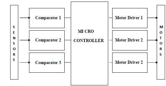
At initial position all the wheels are on the ground and microcontroller is programmed in such a way that the robo moves forward till the sensor circuit detect any obstruction. The sensor circuit consist of IR LED and phototransistor .The IR LED emits the IR radiations ,when there no obstruction the phototransistor does not detect any reflected radiation and the vehicle moves forward without any vertical motion.
When any obstruction comes in front of sensor mounted in front of wheel one the IR radiation are reflected back from the obstruction which is picked up by phototransistor .This phototransistor supplies a trigger signal to the comparator which conditions the signal and supplies the signal to microcontroller. The forward motion of the robo stops and microcontroller then detect the signal on a programmed pin. According to programming controller send the signal to the motor driver .
The motor driver drives the rack and pinion which lifts the wheel set one from the ground. The phototransistor detect the radiated IR radiations till the IR LED moves above the obstacle. As the wheels thus IR LED moves above the obstruction no sensor detect any signal thus forward motion of robo is initiated by the controller. Now the second detector detect the obstruction and same action is repeated as in case of first sensor. Once the second wheel moves over the obstruction the center of gravity moves in such a position that robo cannot topple. Thus in similar way third and last wheel climb over the obstruction and the robo moves above the obstruction.
The report details the implementation of distance measurement system using the ultrasonic waves. As the human ear’s audible perception range is 20 Hz to 20 kHz, it is insensitive to ultrasonic waves, and hence the ultrasound waves can be used for applications in industries/vehicles without hindering human activity. They are widely used as range meters and proximity detectors in industries also it can be used in parking assistance system. The distance can be measured using pulse echo and phase measurement method. Here the pulse echo method is used. The measurement unit uses a continuous signal in the transmission frequency range of ultrasonic transducers. The signal is transmitted by an ultrasonic transducer, reflected by an obstacle and received by another transducer where the signal is detected. The time delay of the transmitted and the received signal corresponds to the distance between the system and the obstacle.
The techniques of distance measurement using ultrasonic in air include continuous wave and pulse echo technique. In the pulse echo method, a burst of pulses is sent through the transmission medium and is reflected by an object kept at specified distance. The time taken for the pulse to propagate from transmitter to receiver is proportional to the distance of object. For
contact less measurement of distance, the device has to rely on the target to reflect the pulse back to itself. The target needs to have a proper orientation that is it needs to be perpendicular to the direction of propagation of the pulses. The amlitude of the received signal gets significantly attenuated and is a function of nature of the medium and the distance between the transmitter and target. The pulse echo or time-of-flight method of range measurement is subject to high levels of signal attenuation when used in an air medium, thus limiting its distance range.
Design procedure
The circuit has been divided into two divisions.
(i) Digital section- micro controller and LCD display unit with 5volt power supply
(ii) Analog section –
(a) Transmitting side - Ultrasonic transducers, gain amplifier using uA741 CD4066
CMOS analog switch.
(b) Receiving side - TL084 comparator, gain amplifier, voltage limiter.
(c) +15V and -15V power supply.
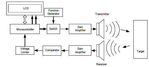
The time of flight method is used for finding the distance between the transmitter and the object. The transmitter sends out a burst of pulses and a receiver detects the reflected echo. The time delay between the corresponding edges of the transmitted and received pulses is measured by microcontroller, this gives the time of flight. Substituting the time delay and the velocity of ultrasound in air (330 metres/second) in the following formula we can determine the distance between the transmitter and the target. Fig.2 shows the transmitted and received pulses.
Distance = Velocity X Elapsed time
Solar panels are one of the most economical and low-maintenance forms of producing since they don't have any moving components. Despite...

