
Here is a simple project more useful in
watering plants automatically without any human interference. We may
call it as Automatic plant irrigation system. We know that people do not
pour the water on to the plants in their gardens when they go to
vacation or often forget to water plants. As a result, there is a chance
to get the plants damaged. This project is an excellent solution for
such kind of problems.
Block Diagram of Automatic Plant Irrigation System:
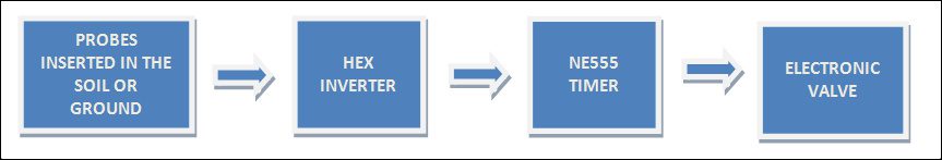
- Circuit is not that much complicated. We use the basic concept in this circuit i.e. soil have high resistance when it is dry and has very low resistance when it is wet.
- By using this concept we will make the system work. We insert two probes in the soil in such a way that that they will conduct when the soil is wet and they will not conduct when the soil is dry. So, when the probes do not conduct, system will automatically detect this condition with the help of HEX inverter which will become high when the input is low.
- HEX inverter will trigger the NE555 Timer and this NE555 timer will trigger another NE555 which is connected to the output of first NE555. Now the second NE555 which is configured as astable multivibrator will help to switch on the Electric valve and as result, it will allow the water to flow to the soil.
- When the water wet the soil, probes will again conduct and make the output of 7404 low which will make the first NE555 to low and also drive remaining circuit to low. So, automatically it will switch off the valve.
Main Components in Automatic Plant Irrigation System:
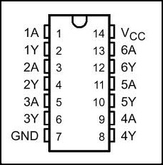
Hex Inverter 7404: the
main function of the inverter is to give the complemented output for its
input i.e. it will give output which is opposite to input. For example,
if the input is low to the inverter, then the output will be high. Just
like the normal inverter which gives high output when the input is low
and gives low output when the input is high. 7404 IC will be having six
independent inverters; Operating supply voltage is around 4.75V minimum
to 5.5V maximum, normal supply voltage is 5V. They are used in different
applications like inverting buffers, drivers, hex inverters etc. 7404
IC will be available in different packages like DIP (dual inline
package), QFP (Quad Flat Package) etc. The pin configuration of Hex
Inverter 7404 is shown below.
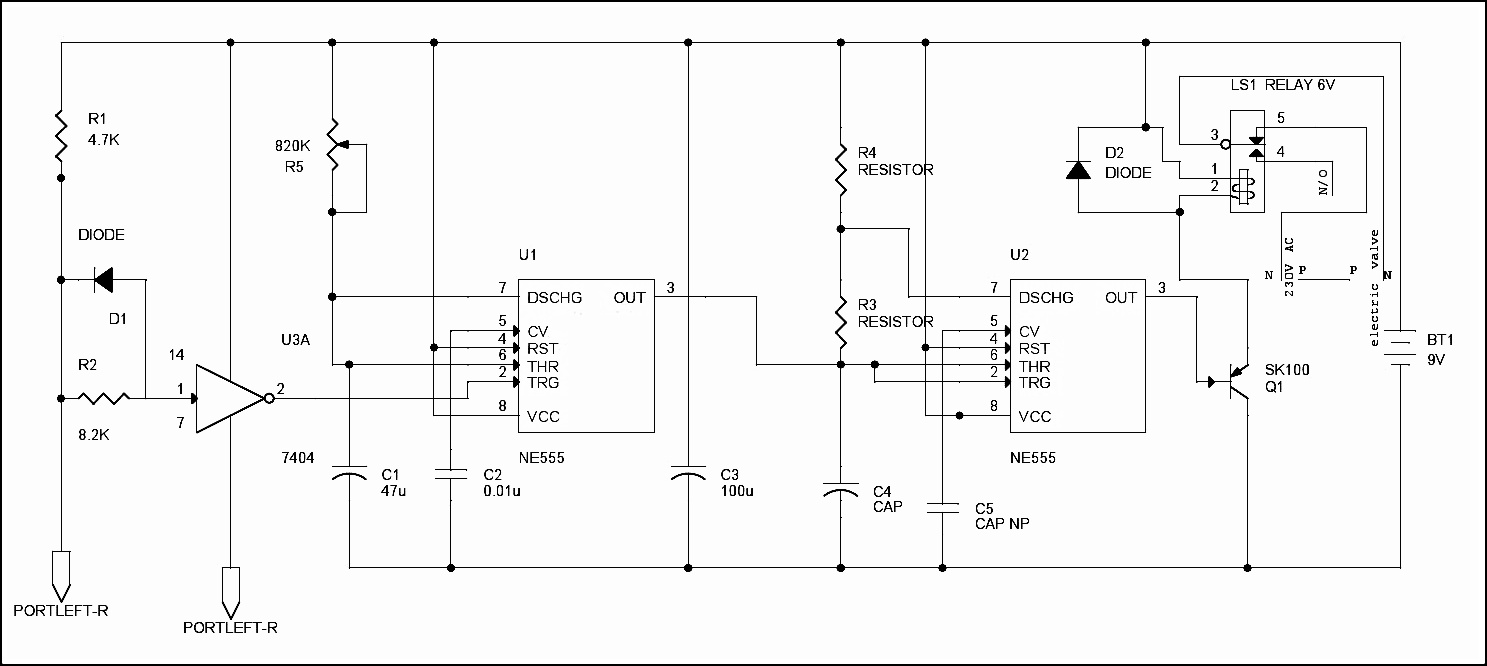
Circuit Diagram of Automatic Plant Irrigation System:
Circuit Explanation:
- We are all well aware that the plants will die due to lack of water in the soil. Soil will have high resistance when it is dry and it will have very low resistance when soil is wet. We use this simple logic to water the plants and make the circuit work.
- Two probes which are connected to the circuit are placed into the soil. The two probes will conduct only when soil is wet (resistance is low) and they cannot conduct when soil is dry due to high resistance. The voltage is given to the probes to conduct is given from the battery connected to the circuit.
- When the soil is dry it will produce large voltage drop due to high resistance. This is sensed by 7404 hex inverter and makes the first NE555 timer trigger which is configured as monostable multivibrator with the help of a electrical signal.
- When the first NE555 is triggered at pin 2, it will generate the output at pin 3 which is given to the input of second NE555 timer. The second 555 timer is configured as astable multivibrator which got triggered by the first 555 timer and will generate the output and drive the relay which is connected to the electrically operated value through the transistor SK100. You can use a heat sink for SK100 transistor if it is dissipating more heat.
- The output of second NE555 timer will switch on the transistor SK100 which will drive the relay. Relay which is connected to the input of electrical value and output of value is given to the plant plots through the pipe.
- When transistor has turned on relay, it will open the valve and water is poured on to the plants pot. When the water content in the soil is increased, the resistance in the soil will get decreased and conduction of the probes will get started which will make the 7404 Inverter to stop the triggering of first 555 timer. Ultimately it will stop the electrical valve which is connected to the relay. Variable resistor (R5) and capacitor (C1) are used to adjust the valve when to we want to conduct the probes.
- The capacitor C5 (0.01uf) is used to ground, the CV pin of second NE555 timer. C3 will remove the AC noise and allow only DC to the remaining circuit. C4 and R3 will constitute to configure the NE555 in astable multivibrator.
- Capacitor (C4) = 10u 16V.
- Capacitor (C5) = 0.01u.
- Resistor (R3) = 27K
- Resistor (R4) = 27K
- Diode (D1 and D2) = IN4148
- Relay = 6V, 150 ohms


I am extremely impressed along with your writing abilities, Thanks for this great share.
ReplyDelete