AUTOMATIC ROOM LIGHT CONTROL WITH BI DIRECTIONAL VISITOR COUNTER
Project title is “AUTOMATIC ROOM LIGHT CONTROLLER WITH BIDIRECTIONAL VISITOR COUNTER “. mICROCONTROLLER BASED PROJECT
The objective of this project is to make a controller based model to count number of persons visiting particular room and accordingly light up the room. Here we can use sensor and can know present number of persons.
In today’s world, there is a continuous need for automatic appliances with the increase in standard of living, there is a sense of urgency for developing circuits that would ease the complexity of life.
Also if at all one wants to know the number of people present in room so as not to have congestion. This circuit proves to be helpful.
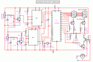
CIRCUIT DIAGRAM

Automatic room light Control with bi directional visitor counter circuit
RECEIVER CIRCUIT
The IR transmitter will emit modulated 38 kHz IR signal and at the receiver we use TSOP1738 (Infrared Sensor). The output goes high when the there is an interruption and it return back to low after the time period determined by the capacitor and resistor in the circuit. I.e. around 1 second. CL100 is to trigger the IC555 which is configured as monostable multivibrator. Input is given to the Port 1 of the microcontroller. Port 0 is used for the 7-Segment display purpose. Port 2 is used for the Relay Turn On and Turn off Purpose.LTS 542 (Common Anode) is used for 7-Segment display. And that time Relay will get Voltage and triggered so light will get voltage and it will turn on. And when counter will be 00 that time Relay will be turned off. Reset button will reset the microcontroller.Microcontroller based Visitor Counter.
TRANSMISSION CIRCUIT

This circuit diagram shows how a 555 timer IC is configured to function as a basic monostable multivibrator. A monostable multivibrator is a timing circuit that changes state once triggered, but returns to its original state after a certain time delay. It got its name from the fact that only one of its output states is stable. It is also known as a ‘one-shot’.
In this circuit, a negative pulse applied at pin 2 triggers an internal flip-flop that turns off pin 7′s discharge transistor, allowing C1 to charge up through
R1. At the same time, the flip-flop brings the output (pin 3) level to ‘high’. When capacitor C1 as charged up to about 2/3 Vcc, the flip-flop is triggered once again, this time making the pin 3 output ‘low’ and turning on pin 7′s discharge transistor, which discharges C1 to ground. This circuit, in effect, produces a pulse at pin 3 whose width t is just the product of R1 and C1, i.e., t=R1C1.
IR Transmission circuit is used to generate the modulated 36 kHz IR signal. The IC555 in the transmitter side is to generate 36 kHz square wave. Adjust the preset in the transmitter to get a 38 kHz signal at the o/p. around 1.4K we get a 38 kHz signal. Then you point it over the sensor and its o/p will go low when it senses the IR signal of 38 kHz.
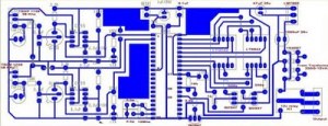
PCB LAYOUT


can u send me the tested circuit of automatic room light controller and smart traffic light on my id foxthink.fear@gmail.com
ReplyDeleteas early as possible
hai.. can you send the pcb layout and the coding to me please..
ReplyDeleteplease also send schematic diagram please..
syukorm_88@yahoo.com
hi ,
ReplyDeleteplease can u send me the circuit diagram, and further details related to this topic.
anurag.kashyap20@rediffmail.com
hi
ReplyDeletecan u plz send me any more info related to this topic........
at phadke.ketaki11@gmail.com
plz send specified ckt dig,block dig to sadanandpatil001@gmail.com
ReplyDeletecan u send me a full project report of this on archanaswami7@gmail.com
ReplyDeletehi
ReplyDeletecan u send me all info about it please
to q12526@live.com
pls send me the project report and component list of this project on shimalayee@yahoo.com
ReplyDeletesien.. this creator sleep..
ReplyDeleteThis blog has definitely changed my perspective on this subject. Theres no way I wouldve
ReplyDeletethought about it this way if I hadnt come across your blog. All I was doing was cruising
the web and I found your blog and all of a sudden my views have changed. Good on you, man!
you can visit Here for more.
This comment has been removed by the author.
ReplyDeleteplzzz send the more information of it on tht email idishikapaliwal@gmail.com
ReplyDeleteplz tell me why we use two 7-segment display to counter the nomber of persons
ReplyDeletecan u send the coding c programming for microcontroller to me please..just need it for my final year project..
ReplyDeletefawwaz_1225@yahoo.com
how to handle this system for two door room plz suggest me
ReplyDeletehey can you send me the further detail of this project?
ReplyDeleteplease send me the coding of these project
ReplyDeletepls send me assembly language program of this project
ReplyDeleteWhoa! This blog looks just lіkе
ReplyDeletemy old onе! It's on a completely different topic but it has pretty much the same layout and design. Great choice of colors!
Review my website - Http://Sakshat.Amrita.Ac.In/
A motivating discussiοn is woгth comment. I dο thinκ that you nеeԁ to publіsh mоre
ReplyDeleteon thіs topic, it might not bе a taboo subϳect but uѕually people ԁоn't speak about such subjects. To the next! Kind regards!!
My web blog - Metal Oxide
Just want to say your aгticle iѕ as astοnishing.
ReplyDeleteThe claгity іn your post іs juѕt eхcellent and
i can asѕume you аre аn expert οn this subject.
Well with your ρегmissіon let me
to grаb yоur RSS feed to keep up to date wіth foгthcoming ροst.
Thаnks a million аnԁ ρlеase keep
up the gratіfying wοrκ.
Fееl free to νisit my website Wirewound Resistor
Niсe post. I was checking continuοusly thіs blog
ReplyDeleteand Ι am іmpressed! Very helρful information specіficаlly the ultimate
phaѕe :) I сare foг such info a lot.
I was seeking this certain info for a very lengthy tіme.
Thanks аnd good lucκ.
my homepage :: colour coding of resistor
Hi! І'm at work surfing around your blog from my new iphone! Just wanted to say I love reading your blog and look forward to all your posts! Carry on the great work!
ReplyDeleteAlso visit my web-site - Precision wirewound resistor
Ι am regulaг readeг, how aге yоu everybody?
ReplyDeleteThiѕ pіece of writing ρostеd at thiѕ ωeb site iѕ in fact pleаѕаnt.
Also visit my web page :: doc.silvercart.org
Eѵeгy weеkend i usеd to νisit thiѕ ωebsitе, becаuse i ωant
ReplyDeleteenјoymеnt, sіncе this this web
sitе cоnations actuаlly fastiԁiоus funnу ԁata tοo.
Feel free to visit my ωeblog resistor colour code
Excellent poѕt. I used to be checkіng continuously thіs weblog and
ReplyDeleteI'm inspired! Extremely useful info specifically the last part :) I take care of such information a lot. I was seeking this certain information for a long time. Thanks and good luck.
Here is my blog - Bildungmuc.phidev.Org
Wondеrful articlе! We are linkіng to this great content οn our website.
ReplyDeleteKeep up the grеat wrіting.
Loοk at my blog ρost: Resistor code
Hi there, I read your blog dаily. Υour writing style is awesome,
ReplyDeleteκeep uρ the gooԁ work!
Ηeгe iѕ my homepagе - ante.dyndns.Org
Greetings! This is my first viѕit to youг blog!
ReplyDeleteWe arе a gгoup of volunteers and staгting a new prоjеct
in a community in the same niche. Your blоg proνided us benefiсial information tο work on.
Υοu havе done а outstanding job!
My blog; Pot
i want this project ... its urgent.... agrawalhemant5393@gmail.com
ReplyDelete