An extremely creative technology that will assist to keep cities clean is the IOT Garbage Monitoring system. This system keeps an eye on the trash cans and provides information through a web page on the amount of trash being gathered in the cans. The device does this by detecting the rubbish level and comparing it to the depth of the garbage containers using ultrasonic sensors positioned above the bins. The system uses a microcontroller from the AVR family, an LCD display, a WiFi modem to relay data, and a buzzer. A transformer with a 12V output powers the device. The status of the amount of waste collected in the bins is shown on the LCD panel. A web page, however, is created so that the person who is watching it may see the status. The website displays a visual of the trash cans and emphasises the waste that has been collected in colour to demonstrate how much garbage has been gathered. The waste level status is shown on the LCD panel. When the amount of rubbish being collected exceeds the predetermined limit, the system activates the buzzer. Thus, by presenting a graphical depiction of the bins through the IOT Gecko web development platform, this system aids in keeping the city clean by notifying about the waste levels of the bins.
Popular Posts
-
RESEQUENCING ANALYSIS OF STOP-AND-WAIT ARQ FOR PARALLEL MULTICHANNEL COMMUNICATIONS:--DOTNET--2009 RESEQUENCING ANALYSIS OF STOP-AND-WAIT AR...
-
Introduction This amplifier does not claim to be "state of the art", and in fact the base design is now over 20 years old. It is ...
-
Signals, including those used for communication between occupants of a car or train.Indicators, recorders, telegraphic, telephonic, or oth...
Saturday, 25 June 2022
Sunday, 22 June 2014
Auto Night Lamp Using High Power LED
Pull Pin Security Alarm System
Wednesday, 6 June 2012
Digital Stethoscope
Overview
The overall architecture of the system is centered on the ATmega644 microcontroller. The acoustic sensor and keypad are inputs to the MCU, while the LCD, headphones, and MATLAB visualization tool are outputs. Communication with the Flash memory is bi-directional. Figure 2 shows an overview of the system high level design.
Figure 2. System High Level Design
The MCU runs several software interfaces to support the various features of the digital stethoscope. The signal capturing interface uses the analog-to-digital converter to sample the acoustic sensor at 8 kHz. The real-time audio processing module modifies the measured signal based on user settings and outputs it to the 3.5 mm audio socket via pulse-width modulation. The user interface supports the detection and de-bouncing of keypad button presses as well as controls the LCD display to reflect the current state of the system. In addition, the user interface also outputs real-time or recorded data at 100 Hz to a MATLAB utility running on a separate PC for signal visualization and average heart rate calculations. The Flash interface includes a software library for SPI communication to read from and write data to the external Flash memory chip.
Sunday, 6 May 2012
Gas Leak Detection
Abstract
The aim of the project is to develop a gas leak detection and location system for the production safety in Petrochemical Industry.
PURPOSE:
The purpose of the project is to monitor gas leakage parameter. When they exceeds threshold, intimation is given to the nearby control section including readings of parameter and location of the gas leakage.
Description:
The system is based on Wireless Sensor Networks (WSN) it can collect the data of monitoring sites wirelessly and sent to the computer to update values and the location also. Consequently, it can give a real time detective of the potential risk area, collect the data of a leak accident and locate the leakage point. However the former systems cannot react in time even cannot obtain data from an accident and locate accurately.
The paper has three parts, first, gives the overall system design, and then provides the approaches on both hardware and software to achieve it. The gas leak detection and location system consists of three parts: control center and terminal nodes.
Here the supervising control center is based on arm controller, it displays the location and the status messages of parameters of all the monitoring sites, and it is a graphical description of the geographical information of the entire potential risk area. Status, sensor data and location data, and then sent them to the control center to update value in the location software
TECHNOLOGY:
Zigbee is new wireless technology guided by IEEE 802.15.4 Personal Area Network standard. It is primarily designed for the wide range controlling applications and to replace the existing non-standard technologies. It currently operates in 868 MHz band at a data rate of 20Kbps in Europe, 914MHz band at 40kbps in USA, and the 2.4GHz ISM bands Worldwide at a maximum data-rate of 250kbps. It is used to verify whether user's truncation is possible or not. One of the main advantages of this ZIGBEE communication is that it provides a noise free communication, the amount of noise added in this type of communication is very less compared to the other wireless communications
RESULT:
Hence a gas leak detection and location system for the production safety in Petrochemical Industry was designedAttendance Management Using Face Recognition System
The aim of this project is to deal with the problem of face detection in color images. Unlike in face recognition, where the classes to be discriminated are different faces in face detection, the two respective classes are the “Face area” and the “Non face area”. The novel approach to face detection is presented, binarisation rules especially designed for a skin area detection within a image frame.
The process involves Binarisation, localization, training and identification of Human Face.
This project easily extract the human face from any other images. Image segmentation algorithm is used to identify the face from other images.
After recognizing the face, the PC puts the attendance for the particular user. Also it sends signal to the microcontroller through serial port. The microcontroller analyses the signal and operates the door motor through driver section. The microcontroller program is written in assembly language. The microcontroller used is PIC 16F73
In this project, the camera is replaced by CD drive. The face is stored in the CD. As soon as the particular CD is inserted, the software in the PC recognizes the face and sends signal to the microcontroller through serial port. The PC recognizes the face and checks the data with the existing data. If it matches with any data, it puts attendance for the particular user. Also it sends signal to the microcontroller
The microcontroller used in this circuit is PIC16F73. It is a 28 pin IC with three I/O ports. It has inbuilt ADC. According to the signal received from the camera, the values are stored in the RAM of the microcontroller. Accordingly the microcontroller controls the door motor through driver section and relay. The microcontroller program is written in assembly language. The assembly language program is compiled to form “hex” code. The “hex” code is written in the microcontroller using PIC write software with the help of PIC writer.
Bluetooth Energy Meter
Abstract
The word automation brings to mind devices that operate with minimal human intervention. In other words, acting or operating in a manner essentially independent of external influence or control. It finds application in controlling industrial equipments, home appliances, computer peripherals and robots. Bluetooth is a promising new wireless technology, which enables portable devices to form short-range wireless ad hoc networks and is based on a frequency hopping physical layer. Bluetooth is a frequency hopping system, which defines multiple channels for communication (each channel defined by a different frequency hopping sequence). A group of devices sharing a common channel is called a piconet. Each piconet has a master unit, which selects a frequency hopping sequence for the piconet and controls the access to the channel. Other participants of the group known as slave units are synchronized to the hopping sequence of the piconet master
Home and office automation using Bluetooth enabled devices have generated sufficient interest in the networking community. Bluetooth based automation offers flexibility, even when the devices actually present far from the master unit. The commands for the automation unit are given through the software module in PC. From PC the command is given to Bluetooth USB adapter. The Bluetooth USB adapter enables the Bluetooth communication and converts the data into airborne signals. The Bluetooth transceiver has a built-in antenna receives the air borne signals and transfer the data to the embedded controller through serial port. The Bluetooth transceivers can be operated in point-to-point, point-to-multipoint and multipoint-to-multipoint architectures.
The embedded microcontroller is programmed to read the data. The embedded controller is the CPU that decides the operation of the automation unit. The embedded controller used here is 89C51 microcontroller. It is a derivative of 8051 microcontroller whose architecture and instruction set are same as 8051 microcontroller with some additional functionality. Since the controller has the inbuilt peripherals it is called as embedded controller. The embedded controller controls the automation unit as per the commands. Bluetooth based systems are developed to manage proper safeguards to prevent unauthorized leakage of information. Synchronizing data between cell phones, laptops, and PDAs; using cell phones as cordless phones when at home; and connecting PDAs to the office LAN are some of the cumbersome things that are possible with Bluetooth
Design of a Wireless Medical Monitoring System
Abstract
The main aim of this project is used Monitoring Terminal and it can detect the patient's real-time body temperature, heart rate and other physiological informations, and transmit them to the control center.
PURPOSE :
DESCRIPTION:
Now a day with the increase of biomedical sensor we are going into this process of detecting the patient's real-time body temperature, heart rate and other physiological information's .Coming to the main core of wireless medical monitoring system is the design of wireless monitoring terminal, and the development of system software. The monitoring terminal generally consists of three modules: the sensor module, the control module, and the wireless communication module. The sensor module is used for acquiring medical information from the outside, and then converts them to digital signals. The control module is often compared to the brain of monitoring terminal, which is in charge of coordinating the task of different modules, controlling the sensors, processing data, and executing communication protocols.
The wireless communication module mainly deals with the wireless transmission of information. Nowadays, there are various kinds of wireless communication protocols. But since the main task of a monitoring terminal is to realize the transmission of signals such as heart rate, body temperature, and calling signals the data traffic is not heavy. Moreover, because the monitoring terminal is worn on patients, which needs to be supplied by battery, it puts a high demand on the reducing of power dissipation of wireless transmission module. Having taken these comprehensive factors into consideration, this paper chooses the ZigBee technology as the wireless communication protocol. ZigBee technology is a shortrange, low-rate, low-power wireless communication technology
TECHNOLOGY:
Zigbee is new wireless technology guided by IEEE 802.15.4 Personal Area Network standard. It is primarily designed for the wide range controlling applications and to replace the existing non-standard technologies. It currently operates in 868 MHz band at a data rate of 20Kbps in Europe, 914MHz band at 40kbps in USA, and the 2.4GHz ISM bands Worldwide at a maximum data-rate of 250kbps. It is used to verify whether user's truncation is possible or not. One of the main advantages of this ZIGBEE communication is that it provides a noise free communication, the amount of noise added in this type of communication is very less compared to the other wireless communications
Hence, by implementing this project the monitoring terminal can precisely check the heart rate and body temperature of patients, and send them to coordinator and then surveillance center through wireless network.
Solar Based Electromagnetic Braking System
The objective of this project is to design the solar based Electromagnetic breaking system using Object sensor for Automobiles. This project is mainly used in Vehicles either two or four wheelers. In this project is used in real time we can avoid so many accidents.
Brief Methodology:
This project is designed by following blocks
• Microcontroller
• Solar panel with battery.
• Object sensor
• Driver circuit
• Relay
• Electromagnetic core
• Breaking system
The object sensor senses the object and gives corresponding signals. These electrical signals are very small mill voltage signal, so it is given to amplifier circuit. The amplifier circuit is constructed with operational amplifier which acts as power amplifier. Then the amplifier signal is given to signal conditioning unit which also constructed with operational amplifier. In this circuit operational amplifier act as comparator and generate the square pulse given to microcontroller. The microcontroller may be ATMEL/PIC/RENESAS/ARM microcontroller. It will work according to our object already we have programmed.
According to the object sensor value, the microcontroller activates the driver circuit as per mentioned in the program. The driver circuit is constructed with transistor which acts as switch to control the relay. The relay output is directly connected to the electromagnetic core which is attached in the breaking system.
Whenever we control the brake, at the time what happens in the system means one of the coil winding is placed around it. It generates the electromotive force and it's fitted with the suitable mechanical set. Likewise when we release the break the force generation will be stopped and the coil winding releases from the mechanical set.
Advantage:
- Can use all type of vehicles
- Low cost
- Low power consumption
Body Motion Information Collection
Abstract
This project is utilizes multiple- Knot network technology to gather multiple –point accelerations information's.
PURPOSE:
This paper deals with the Numerous experiment data indicate it gather accurate information about human body which reflect the truthfully human body motions and this paper is process or transmit it to advanced comprehensively analyzed and this is widely used in such fields are health recovery training, physical exercises, computer games controlling. And here some mathematical calculations about the acceleration component information such as motional track and dynamic process will be gotten for this platform
Description:
Any human body motion, from its beginning to the end, the acceleration of every part of the mobile limbs or other parts of human body is keeping changing. If certain motion is repeated, then its acceleration changing regularity is also very also very close. Therefore if a three-axis acceleration sensor is put on some typical point of measured limbs or other body parts, then the three acceleration components X_Y_Z of that typical point in the motion process can be collected accurately.
Then by mathematical calculation about the acceleration components information such as the motional track and dynamic process about that point will be gotten.
From comprehensive analysis of the data gathered about several typical points detailed information about the measured human body motions is obtained so that motion information is digitalized.
This motion information collection platform uses multi-knot internet technology to
TECHNOLOGY:
Micro-Electro-Mechanical Systems (MEMS) is the integration of mechanical elements, sensors, actuators, and electronics on a common silicon substrate through microfabrication technology. While the electronics are fabricated using integrated circuit (IC) process sequences (e.g., CMOS, Bipolar, or BICMOS processes), the micromechanical components are fabricated using compatible "micromachining" processes that selectively etch away parts of the silicon wafer or add new structural layers to form the mechanical and electromechanical devices.
RESULT:
By this controller we get the information according to motion of the body.
SMS Controlled Industrial Controller
In a process control industry, it is very difficult for a person to be present or to monitors the system continuously. If not, there occurs damage in the whole process industry. In order to view the process continuously and to check the status of the process we are going to use our project “SMS CONTROLLED INDUSTRIAL CONTROLLER”. This project has been implemented in various platforms, now we are going to do this project using LABVIEW Here we can monitor any number of process parameters. The hardware unit consists of all the hardware requirements needed for the process.
This project is implemented by using LABVIEW software to send the message when there prevails any deviation in the process station. Suppose to say, if we are monitoring eight parameters we have to set the limits for all the parameters so that if any parameter value goes out of range then the corresponding message will be sent to the operator indicating there is a deviation in the process.
The parameters like temperature, voltage, speed, current, level, pressure etc. can be measured by using the LABVIEW software. The hardware unit is interfaced with the system using LPT terminal to PC. In our program we have to enable the parallel port mode by setting the appropriate register values to the port. By using ADC configuration using the program, data acquisitions from different channels are performed. Plotting the graphs for these values with respect to time.
If the parameter value goes out of range, then the message is sent to the operator. One mobile is connected to the PC that is having the hardware interface unit and the other one will be with the operator. To send the message to the other user, we have to do the following settings. First of all we have to establish serial communication using VISA card. After setting the serial communication mode, enter the phone number and the message that has to be sent. This will indicate only if there is any deviation in the parameter value. We can also use buzzer to get ON whenever the data's acquired goes out of range by using DIGITAL OUTPUT configuration using the LABVIEW program.
For this we have to out the data as 1 or 0 to ON and OFF the buzzer unit for indication purpose. The hardware unit is interfaced with the PC by accessing the parallel port and the mobile phone is connected with the PC by accessing the serial port. The Speed parameter can be measured and controlled by using DAC configuration in lab view. Initially set the motor speed at a particular rpm by using the above said mode by counting the data from 00 to FF. By using DIGITAL INPUT configuration, count the number of pulses for every five seconds and convert it into rpm. Compare the current speed with the set speed and out the data using DAC configuration and monitor the speed value in the PC through LPT terminal. If the parameter value goes out of range, then the message is sent to the operator
APPLICATION:-
• This project is very useful in the industrial application
Sunday, 29 April 2012
Automated Step Climber
Human body is perfect combination of motion, balance, co-ordination and reflex. It because human brain is so much developed that all these activities can take place in such perfect co-ordination. With advancement in science we humans have created many beautiful creations and robot happens to be one of them. Humans have developed robots that can mimic humans. In the same context it is our humble effort to develop an electro-mechanical autonomous robotic vehicle that can have multiple degree of freedom, which enable it to move through various terrains.
Taking inspiration from NASA’s path finder robot we have tried to make a tone down prototype which control its movement with help of microcontroller which properly co-ordinate its motion. In our project we have tried to built an electro-mechanical autonomous robotic vehicle, which moves over the hurdles in front of it by sensing obstacle with help of sensing circuit and taking controlled action with microcontroller ,which drives the motors to make robot climb over the obstruction.
We have used many other chips to achieve this motion which we have described in the component section. This robotic vehicle could become a prototype for surveillance vehicle and other military vehicles used for detection and detonation of mines .Since cost of this prototype is very less thus it could be inducted in army easily and be made indigenously.Mainly ou project is based on working of microcontroller for the automatic management and motors for hardware management.
At initial position all the wheels are on the ground and microcontroller is programmed in such a way that the robo moves forward till the sensor circuit detect any obstruction. The sensor circuit consist of IR LED and phototransistor .The IR LED emits the IR radiations ,when there no obstruction the phototransistor does not detect any reflected radiation and the vehicle moves forward without any vertical motion.
When any obstruction comes in front of sensor mounted in front of wheel one the IR radiation are reflected back from the obstruction which is picked up by phototransistor .This phototransistor supplies a trigger signal to the comparator which conditions the signal and supplies the signal to microcontroller. The forward motion of the robo stops and microcontroller then detect the signal on a programmed pin. According to programming controller send the signal to the motor driver .
The motor driver drives the rack and pinion which lifts the wheel set one from the ground. The phototransistor detect the radiated IR radiations till the IR LED moves above the obstacle. As the wheels thus IR LED moves above the obstruction no sensor detect any signal thus forward motion of robo is initiated by the controller. Now the second detector detect the obstruction and same action is repeated as in case of first sensor. Once the second wheel moves over the obstruction the center of gravity moves in such a position that robo cannot topple. Thus in similar way third and last wheel climb over the obstruction and the robo moves above the obstruction.
Monday, 9 April 2012
Heat Control System
Introduction
This project was the first stage of developing a controller for a radiant floor heat system. The microcontroller will use inputs from thermostats, thermocouples, a flow meter, and pressure switches to control the operation of the pumps and valves to achieve improved efficiency of the system as a whole.
This project idea came from a friend who recently built a house which utilizes an outdoor wood boiler for heating. He expressed that he was disappointed in the efficiency of the current system and wished he had more control over the system operation. This seemed like a good application of what I�ve learned in this course. The main goal is to improve the efficiency of the system by shortening the amount of time that the Pumps need to run while still properly heating the home. By doing this, consumption of both electricity and wood will be reduced.
Implementation of this project involves a large amount of work outside of the microprocessor. Because of this, I bound the scope of this academic project to the control logic only. In order to implement this in the house, I will have to build the circuitry to translate the control logic over to the voltages necessary for operation of the valves, pumps and sensors. In order to verify and validate the controller logic worked as desired I built a demonstration board that models the inputs and outputs of the system. This board was used to debug the controls during development and it was also a convenient way of demonstrating this project at the end of the semester. Toggle switches were used to model the 5 thermostats, adjustable voltage dividers were used for thermocouples, a 555 Timer circuit was used for the flow meter and LEDs were used for all outputs.
Thursday, 12 January 2012
final year engineerig project topics
Quasi-Z-Source Inverter for Photovoltaic Power Generation Systems - 2009
Power Injection System for Photovoltaic Generation Plants with Active FilteringCapability - 2009
The Electronic Ballast Using Class-E Rectifier with Tapped Inductor for Power Factor Correction - 2008
A Novel Reference Compensation Current Strategy for Three-phase Three-level Unity PF Rectifier - 2009
Single-Stage Soft-Switching Converter With Boost Type of Active Clamp for Wide Input Voltage Ranges - 2009
Transformer less DC
DC Converters With High Step-Up Voltage Gain used for photovoltaic interface Application - 2009
A Zero-Voltage-Switching Bidirectional DC
DC Converter With State Analysis and Soft- Switching-Oriented Design Consideration - 2009
Soft-Switching Capability Analysis of a Dual Active Bridge Dc-Dc Converter - 2009
Comparison of Control Methods for High-Voltage High-Power Three-Level Half-Bridge DC/DC Converters - 2009
Design of High Voltage, High Power and High Frequency Transformer in LCC Resonant Converter
2009LCC Resonant Converter Operating under Discontinuous Resonant Current Mode in High Voltage, High Power and High Frequency Applications - 2009
Design of LCL-T Resonant Converter Including the Effect of Transformer Winding Capacitance
2009A Non-isolated Bidirectional ZVS-PWM Active Clamped DC
DC Converter - 2009
Analysis and implementation of Single-Switch Quasi-Resonant Converter - 2009
Loss Analysis in Soft Switching Boost Converter using a single switch - 2009
A Novel Soft Switching Flyback Converter with Synchronous Rectification - 2009
Zero-Current-Transition Bridgeless PFC Without Extra Voltage and Current Stress- 2009
An Efficient Common-Mode Hybrid EMI Filter Used in Switch-mode Power Supply - 2009
Active-Clamp ZVS Converter with Step-Up Voltage Conversion Ratio - 2009
Passive and Active Hybrid Integrated EMI Filters - 2009
Modeling and design of a neutral point regulator for a three level diode clampedrectifier - 2009
A novel three-phase PFC rectifier using a harmonic current injection method - 2009
Single-Stage Fly back Converter for Constant Current Output LED Driver with Power Factor Correction - 2009
A Modified SEPIC Converter for High Power Factor Rectifier and Universal-Input Voltage Applications - 2009
A Compensation Technique for Smooth Transitions in Non-inverting Buck-Boost Converter - 2009
A Novel Hybrid Operational Mode Wide Range Input ZVS Front-end Dc-Dc Converter Aiming at Optimized Overall Performance - 2009
A Novel Low-Loss Modulation Strategy for High-Power Bidirectional Buck + Boost Converters - 2009
A Novel ZVZCS LLC-Type Parallel Resonant Converter with A Separated Resonant Tank - 2009
An Interleaved Boost Converter With Zero-Voltage Transition - 2009
Analysis and implementation of Switched-capacitorized DC/DC Converters - 2009
Analysis of Super-Lift Luo-Converters with Capacitor Voltage drop - 2009
Compensation Loop Design of A Photovoltaic System Based on Constant Voltage MPPT- 2009
Design and Comparison of Two Front-end DC/DC Converters: LLC Resonant Converterand Soft-switched Phase-shifted Full-bridge Converter with Primary-side Energy Storage Inductor - 2009
Design Oriented Analysis of Modern Active Droop Controlled Power Supplies - 2009
Distributed Z-Source Network DC-DC Converter - 2009
High-efficiency module-integrated photovoltaic power conditioning system - 2009
Light-Load Efficiency Improvement for Buck Voltage Regulators - 2009
Single-Stage Offline SEPIC Converter with Power Factor Correction to Drive HighBrightness LEDs - 2009
Single-Stage Single-Switch Switched-Capacitor Buck/Buck-Boost-Type Converter - 2009
Stability analysis of two-cell buck converter driven DC motor with a Discrete-Time closed Loop - 2009
Three-Switch Active-Clamp Forward Converter with Low Switch Voltage Stress - 2009
Topology and analysis of Voltage-lift-type Cuk converters: - 2009
engineerig project topics
Fault-Location System for Multiterminal Transmission Lines
A Fuzzy Rule-Based Approach for Islanding Detection in Distributed Generation4.
A Novel Three-Phase to Five-Phase Transformation Using a Special TransformerConnection5.
High-Efficiency Voltage Regulator for Rural Networks6.
Optimized Modulation for AC±DC Harmonic Immunity in VSC HVDCTransmission7.
Optimal Capacitor Placement and Sizing in Unbalanced Distribution Systems WithHarmonics Consideration Using Particle Swarm Optimization8.
Design of a Mode Decoupling STATCOM for Voltage Control of Wind-DrivenInduction Generator Systems9.
A Power-Quality Index to Assess the Impact of Voltage Harmonic Distortions andUnbalance to Three-Phase Induction Motors10.
Power-Management Strategies for a Grid-Connected PV-FC Hybrid System11.
Optimal location and control of shunt FACTS for transmission of renewable energyin large power systems12.
Wind Farm to Weak-Grid Connection using UPQC custom power device13.
Enhancement of power quality in distribution system using D-STATCOM14.
Research on three-level static synchronous compensator15.
Control Scheme of Cascaded H-Bridge STATCOM Using Zero-Sequence Voltageand Negative-Sequence Current16.
Instantaneous power control of D-STATCOM with consideration of power factorcorrection17.
A new 84-pulse VSC configuration using multi-level DC voltage reinjection forespecial applications18.
Non Linear Control of STATCOM19.
A High Performance Induction Motor Drive System Using Fuzzy Logic Controller20.
An Online Simplified Rotor Resistance Estimator for Induction Motors21.
Design of a hybrid PID plus fuzzy controller for speed control of induction motors22.
Design on Vector Control System of AC Motor for Hybrid Electric Vehicles23.
A hybrid system based approach to Direct Torque Control (DTC) of inductionmotors24.
Vector controlled PMSM drive based on fuzzy speed controller25.
Design of controller for PMSM
Single-phase hybrid active power filter using single switch parallel active filter andsimple passive filter27.
Implementation and Control of an Hybrid Multilevel Converter with Floating DC-links for Current Waveform Improvement28.
Harmonic elimination in single phase systems by means of a hybrid series activefilter (HSAF)29.
APF for harmonic voltage resonance suppression in distribution system30.
Dynamic DC-bus voltage control strategies for a three-phase high power shuntactive power filter31.
Control circuit for active power filter with an instantaneous reactive power controlalgorithm modification32.
A hybrid system based approach to Direct Torque Control (DTC) of inductionmotors33.
Torque ripple reduction in direct torque control of induction machines by use of allvoltage vectors of matrix converters34.
Novel Direct Torque Control Based on Space Vector Modulation With AdaptiveStator Flux Observer for Induction Motors35.
Improved Fault-Location System for Railway Distribution System UsingSuperimposed Signal36.
Input-Output Linearization and Robust Sliding-Mode Controller for the VSC-HVDC Transmission Link 37.
ANN-Based SVC Switching at Distribution Level for Minimal-Injected Harmonics38.
Reference Current Computation for Active Power Filters by Running DFTTechniques39.
Dynamic Hysteresis Current Control to Minimize Switching for Three-Phase Four-Leg VSI Topology to Compensate Nonlinear Load40.
Design and Implementation of a Current-Source Converter for Use in IndustryApplications of D-STATCOM41.
Design of a 28 V-to-300 V/12 kW Multicell Interleaved Flyback Converter UsingIntercell Transformers42.
Implementation and Performance Evaluation of a Fast Dynamic Control Schemefor Capacitor-Supported Interline DVR 43.
Effects of Switching Asymmetry on an Isolated Full-Bridge Boost Converter44.
A High-Power-Factor Single-Stage Single-Switch Electronic Ballast for CompactFluorescent Lamps45.
A Three-Phase Interleaved DC±DC Converter With Active Clamp for Fuel Cells46.
Flexible Power Electronic Transformer
47.
Single-Phase AC±AC Converter Based on Quasi-Z-Source Topology48.
An Inrush Mitigation Technique of Load Transformers for the Series Voltage SagCompensator
Friday, 2 December 2011
Micro Controller based Security System using Sonar
and to cover a whole room requires many of these beams. This makes this technology very expensive. It is also by no means foolproof and can be evaded by experts as has been so ably demonstrated in so many Hollywood films. Temperature sensors can also be evaded as they can either be made extremely sensitive and risk false tripping of the alarm due to changes in ambient temperature or made less sensitive at the risk of allowing evasion. The use of SONAR offers us many advantages. It is nearly foolproof, albeit it be at the expense of being extremely sensitive to the point that the only way to avoid tripping of the alarm is to make sure that the room it is covering is free from any movements. In this project we have designed and developed a unique security system that utilises the capabilities of microcontroller and a special purpose SONAR
module. It is also extremely cost-effective when compared to similar systems currently in use.
Smart Fan: A Human Tracking Fan System
The two PIR sensors are separated in the middle. The purpose of this is to separate the sensors’ field of view.
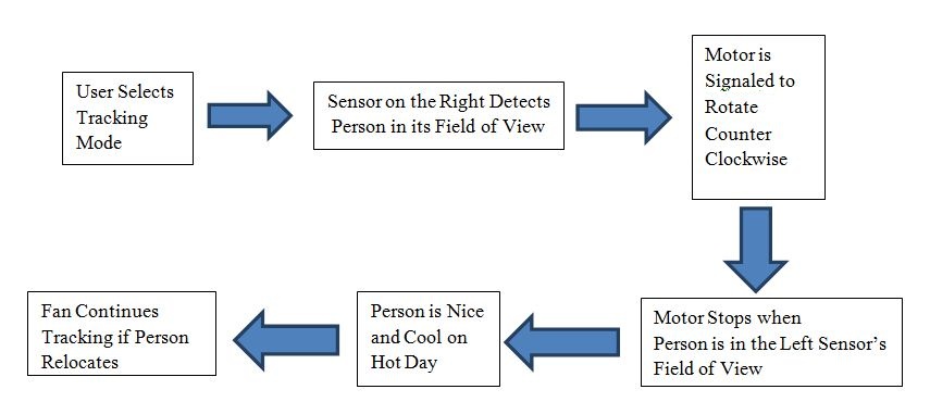
When a sensor detects the right amount of infra-red light a comparator output goes high. We use the microcontroller to generate an interrupt on the comparator’s rising edge. The interrupt then signals a task that begins rotating the platform’s motor. The rotation is clockwise if the left sensor has detected a person or counter clockwise if the right sensor has detected a person. Once the fan is directed at the person’s location, there is just enough infra-red light in the second sensor’s field of view to trigger its comparator. This generates an interrupt that signals a task to either stop or redirect the motor, depending on the setting. At this point the customer is nice and cool without exerting any effort.
An example of the fan’s operation is illustrated in the block diagram below.
LED-Following Car
In our project, the phototransistors sent their outputs to the ATMEL Mega644 microcontroller. The MCU then calculates which motors should move based on the phototransistors and sends a signal to the optoisolators telling which motors to turn on. Depending on which optoisolator is turned on, the motor control will tell which motor to move. We used optoisolators to separate the MCU from the motor circuitry. Optoisolators isolate the LED side of the circuit from the phototransistor side of the circuit, ideally protecting the MCU from any unknown outputs from the motor controller.
Saturday, 19 November 2011
grid tied inverter,grid interactive inverter
A recent development in renewable energy technology is 'grid-interactive' or two way grid interconnection. These systems use sophisticated control equipment so that when your renewable energy system produces more power than you need, the excess power is fed back into the grid i.e. power is exported to the grid. When your system doesn't produce or have enough power, then you draw power from the grid. Some electricity retailers offer 'net billing' arrangements, so that they buy the electricity you produce at the same price as they sell their electricity to you. The renewable electricity is produced as Direct Current (DC). The DC electricity from the panels passes through a grid-interactive inverter, which converts the DC electricity into Alternating Current (AC), which is the type of electricity supplied by the grid
This AC electricity is then used by any appliances operating in the house. If more electricity is produced than the house needs then the excess will be fed into the main electricity grid. Conversely, when the renewable system is not generating enough electricity to power the house, the house will draw power from the grid. Grid interactive systems eliminate the need for a battery backup for when the sun doesn't shine (if it’s a solar system) or the wind doesn't blow (if it’s a wind turbine). In effect, the grid serves as your battery. This means that maintenance costs for your system will be less. It should be noted that without battery storage, a grid connected system will shut down when there is no power on the grid.
Features
- Grid interactive systems
- Low Maintenance Costs
- Eco-Friendly
Monday, 30 May 2011
Egninering project topics
-
Construction of central control unit for Irrigation water pumps. Cost effective method to control entire villagers water pumps with user level authentication. Illiterates friendly system.
- Finger Print and speech recognition based most secured vehicle access control system.
-
Touchscreen based advanced home automation system for next generation apartments.
-
Bluetooth based security enabled powered devices control system.
- Voice recognition and voice guidance based GPS turn-by-turn navigator for blind with ultrasonic obstacle avoidance.
-
Design and development of Mobile phone using Modem, Graphical LCD, buzzer and Touchscreen based keypad.
-
High power LED based intelligent streetlight controlling system with automatic brightness control with vehicle presence sensor.
-
Bluetooth Energy Meter.
- Finger print and keypad based security access system.
-
Touchscreen based Digital Slate for next generation elementary school children.
-
Smartphone Operated Robot.
- Voice Controlled 230v lamp dimmer with 10 levels of intensity control.
-
Google Android Smart phone operated Motor Control System.
-
Android operated Intelligent 230v AC Lamp Dimmer.
-
Smartphone based data logger.
-
Triac and optically isolated diac based electrical oven temperature monitoring and controlling system with zero-crossing detector.
-
Human body temperature and Heartrate monitoring on mobile screen over bluetooth wireless technology.
-
GSM based Irrigation Water Pump Controller for Illiterates. (No Mobile phone operation knowledge required)
-
Implementation of location based advertisement system using GPS and Graphical LCD.
-
Innovative keyboard construction with only one input pin.
-
Voice actuated hospital bed control system. Very useful in operation of selected bed movements and room environment functions associated with a provided multi-function hospital bed.
-
RFID and GSM based intelligent letterbox (mailbox).
- Fingerprint based electronic voting machine.
-
Sooxma's Android phone temperature data logger over bluetooth.
-
Microcontroller based Wireless matchbox with digital lantern.
-
Image based password authentication for Illiterates with Touchscreen.
-
Speaking microcontroller for deaf and dumb.
-
Wireless Google Earth control system at Railway/Bus Stations for tourist’s route map guidance.
-
Virtual wireless dancing bells for classical dancers.
-
Touchscreen based temperature monitoring and control system with graphical LCD.
-
Location driven car music player. (Plays devotional songs near temples, shuts at home etc.)
-
GPS based asset/vehicle/animal/child tracking system.
-
Smart card based prepaid Energy Meter for short term resident housing.
-
Microcontroller and Touchscreen based wireless library book catalog system.
-
Touchscreen based Nurse/attendant calling system for physically impaired.
-
CAN protocol enabled multi-region monitoring and control system.
-
Graphical LCD and Memory stick (MMC/SD card) based textbook reading system.
-
Mobile phone controlled four-legged walking robot with speed and direction control.
-
GPS based universal clock. Gets the time from satellites and displays on GLCD.
-
Microcontroller based online examination system with dynamic questions.
- Biometric Fingerprint and touchscreen keypad based bank locker security access system.
-
Digital vehicle speedometer with password enabled speed limit setting.
-
GPS based vehicle travel location-logging system. This System stores the traveler’s geographical location and speed at an interval of one second and is stored in to 1GB MMC/SD memory card.
-
SMS based remote SIM card’s address book access system.
-
Microcontroller based digital clock with Graphical LCD and Sanskrit font (or Any regional font) Numbers.
-
Microcontroller based virtual boundary/fencing for Wild Animals.
- Voice Controlled AC Fan motor speed control system with 20 levels speed selection.
-
GSM based instantaneous vehicle registration details extraction system very useful for Traffic police.
-
Wireless Heartbeat Monitoring and Alert system.
-
RFID/Mifare/Smart Card based security access control systems.
-
Speech recognition based wheel chair operation and wireless home devices control system.
-
GPS and GSM based real-time vehicle tracking on GoogleEarth (with two GSM Modems)
-
Implementation of wireless sensors network for Wild Fire monitoring system.
-
Real-time Heartbeat Monitoring system with display on Graphical LCD and Voice based alerting system.
-
Touchscreen operated liquid dispensing system.
-
Location aware mobile phone signal strength logger into 2GB memory card (MMC/SD/MircoSD).
-
Infrared (IR) remote controlled Muscle Stimulator with duration and intensity control.
-
GPS based border alert system for fishermen.
-
MEMS Accelerometer based digital photo frame with automatic position/view adjustment system (similar to digital cameras).
-
Construction of Touchscreen based portable Digital Clock.
-
GPS and Graphical display based tourist-guiding system with Touchscreen keyboard input for dynamic location recording. This can be used any where in the world including Sea and Forest locations.
-
Microcontroller and RF transceiver based chatting application with Touchscreen keyboard implementation.
-
Travel assistant for blind with dynamic user input for location based alerts.
-
Telugu Tutor with dynamic text and Images identification for elementary school kids.
-
Micro Electro Mechanical Sensor (MEMS) Accelerometer/Gyroscope based self-balancing robot.
-
Military persons training system that monitors the speed at which they move and records the calculated traveled distance with the time.
-
GPS based office cab monitoring system very useful for the safety of female employees. This system records the travel path and location with timings. Also records the destination of each employee home.
-
GPS based station name announcement and display system for Trains/buses.
-
Microcontroller and voice based alerting system for blind people with GPS enabled location identification.
-
GPS based navigator with location display on Graphical LCD. This provides user to have the location information displayed in any language.
-
Advanced GPS based navigator for illiterates.
-
Live Human being detection wireless remote controlled Robot. (Useful for detection of terrorists hiding inside buildings)
-
RS485 based SCADA system for longer distance powered devices.
-
Radio Frequency based remote controlled robot with wireless video camera mounted on it.
-
Autonomous Robot with artificial vision for obstacle detection.
- Design and construction of voice operated mobile phone for people with no hands. (supports voice operated SIM card address book access and new number dialing)
-
Accelerometer (Gyroscope) Controlled Robot. Accelerometer is MEMS based 3-axis sensor that can sense the tilt in of the 3-diamentions. The robot moment is controlled based on the tilt angle of the robot. No need to press any buttons for robot control.
-
Mobile technology (GSM) based remote monitoring and control of digital Energy meter. Useful for Electricity Department personal for remote meter reading. Also useful to disconnect the power supply to consumer incase of non-payment of electric bill. This is also used to exchange messages like power cut timings with the consumers.
-
Microcontroller and GPS based geographical map drawing instrument. Very useful for Civil engineers.
-
Touchscreen controlled motor speed and direction controlling system.
-
GSM based digital Notice board with display on Monitor or LCD display.
-
PIR based energy conservation system for corporate Computers and lighting system.
-
Remote control of critical software applications with mobile phone.
-
Microcontroller based dual Lithium-ion battery charger with automated charge and discharge cycles.
-
Virtual distance measuring tape with Graphical LCD. Very useful for roads and buildings department. One man operable and works on anywhere on earth.
-
ARM LPC2148/2138 based remote power meter monitoring system.
-
Radio Frequency wireless remote controlled digital camera with high power LED based focusing light. The camera direction can be controlled remotely and the video images can bed seen live on TV.
-
Wireless Speedo meter for boat/ship with speed and location limit alerts.
-
GPS based travel assistant for blind people.
-
Touch Screen based digital devices control system. This project is to build a Graphical LCD Touch Screen interface for switching electrical devices. The controlled devices can be of high voltage or low voltage.
-
GSM Mobile phone controlled intelligent Robot.
-
Automatic Intelligent Plant Watering System.
-
DC Motor Speed and direction control over GSM Mobile/Modem.
-
Mobile phone controlled Street Light monitoring and control system.
-
UPS battery monitoring system over GSM for high availability systems (banking/finance/medical etc).
-
Touchscreen controlled lamp dimmer for next generation apartments.
-
Soil Moisture sensor based intelligent irrigation water pump controlling system with GSM technology.
-
DTMF mobile phone controlled dam water gates controlling system with high-level protection.
-
DC Motor Speed and direction control using RF/IR/Zigbee technologies.
-
Hazardous chemical valve control system with stepper motor and line of site remote control.
-
Contact less Motor speed monitoring on Graphical display with high and low speed alerts.
-
Wireless Bluetooth enabled GPS receiver data logger.
- J2ME Java phone controlled Home Automation.
-
Liquid dispensing system with adjustable quantity for industrial use.
-
Password enabled pre-paid liquid/milk dispensing system.
-
Wireless Energy Meter monitoring system with automatic tariff calculation.
-
Data logger for energy meter with time and KWH readings. Very useful for historical data logging and analysis.
-
Energy meter per-day average, Max and Min Load display on Graphical LCD.
-
High voltage fuse blown indicator with Voice based announcement system.
-
High voltage fuse blown indicator with display on PC with optical isolation between PC and HV bus bars.
-
Voice enabled devices switching for visually impaired.
-
Talking energy (KWH) meter.
-
Control powered devices with mobile phone for free of cost. This secure system works only for predefined phone numbers (eg: owner number).
-
RF transceiver (Zigbee/X-Bee) based energy meter monitoring system. (Energy Meter reading on PC over wireless comm.)
-
Design and construction of Earth fault relay for single phase power system.
- Interactive Talking Vending machine.
-
Transformer oil temperature monitoring with automatic Circuit Breaker operation.
-
GPS Data Logger with Longitude, Latitude, Speed, Time, Number of satellites into fat16/fat32 file system on 2GB memory card.
-
GSM based SCADA (Supervisory Control and Data Acquisition) implementation.
-
SCADA system design and construction for real-time electrical parameter monitoring and control.
-
Wireless power theft monitoring system and indication at local substations.
-
DC Motors speed synchronization for rolling mills.
-
Timer based Electrical Oven temperature monitoring and control for Metal Industries.
-
Timer based automatic power cutoff for industrial sealing/packaging machines.
-
Microcontroller based substation monitoring and control system.
- J2ME Java Enabled mobile phone controlled bluetooth Robot.
-
Frequency Locked Loop DC Motor speed monitoring and control system.
-
Speech recognition system based powered devices control system.
-
Voice operated Elevator/Lift.