Popular Posts

Showing posts with label Electrical Mini Projects Ideas. Show all posts

Saturday, 25 June 2022

Arduino Uno-based IoT Humidity and Temperature Monitoring

 We can control any electrical device in homes and businesses with the Internet of Things (IOT). Additionally, from anywhere in the globe, you may read data from any sensor and visually analyse it. Using an Arduino Uno and an ESP8266-01 module, we can read the temperature and humidity data from the DHT11 sensor and upload it to a ThingSpeak cloud. The Arduino Uno is an MCU that receives temperature and humidity data from a DHT11 sensor, processes it, and sends it to an ESP8266 module. One of the top platforms for the Internet of Things is the WiFi module known as ESP8266. It can send a data packet to the IOT cloud.


For Arduino IoT-based applications, ThingSpeak offers several excellent tools. We can operate our system via the Internet using the Channels and websites supplied by ThingSpeak, and we can monitor our data from anywhere using the ThingSpeak website. ThingSpeak "Collects" the sensor data, "Analyzes and Visualizes" the data, and "Acts" by starting a response. In this article, we will describe how to submit data to the ThingSpeak server using an ESP8266 WiFi module.


Saturday, 25 March 2017

Automatic Irrigation System on Sensing Soil Moisture Content │Smart Irrigation System


In the field of agriculture, use of proper method of irrigation is important. The advantage of using this method is to reduce human intervention and still ensure proper irrigation.

The project uses an 8051 series microcontroller which is programmed to receive the input signal of varying moisture condition of the soil through the sensing arrangement. This is achieved by using an op-amp as comparator which acts as interface between the sensing arrangement and the microcontroller.

Once the controller receives this signal, it generates an output that drives a relay for operating the water pump. An LCD display is also interfaced to the microcontroller to display status of the soil and water pump. The sensing arrangement is made by using two stiff metallic rods inserted into the field at a distance. Connections from the metallic rods are interfaced to the control unit.

The concept in future can be enhanced by integrating GSM technology, such that whenever the water pump switches ON/OFF, an SMS is delivered to the concerned person regarding the status of the pump. We can also control the pump through SMS.

Monday, 20 March 2017

Energy Meter Reading Over Internet

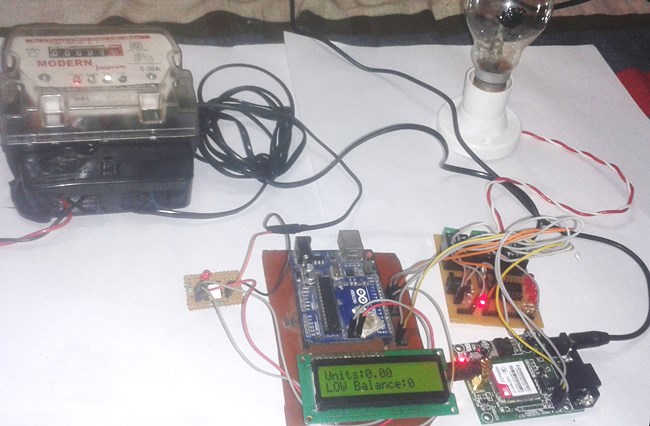
e conventional energy meter reading system may cause low accuracy and low efficiency. This project, energy meter reading over internet facilitates the display of units consumed and cost over the internet (in the form of chart and gauge).


The project block diagram is shown in the above figure which consists of various blocks such as microcontroller, energy meter, LDR, load, LCD display, GSM modem, and power supply block. The digital energy meter used in this project consists of blinking LED (for 1unit it flashes 3200 times) which is interfaced with 8051 microcontroller through LDR. Thus, the LDR generates an interrupt for every LED blink and is fed to microcontroller. The microcontroller takes the reading and displays the same over LCD interfaced with microcontroller.

Sunday, 22 June 2014

Pull Pin Security Alarm System

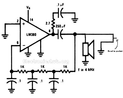
his circuit helps us to get alerted when anybody picks our pockets or bags. The circuit is very helpful to prevent our goods getting pick pocketed. The circuit is called a pull pin security alarm because it gets activated as soon as the pin is pulled.
The arrangement of the circuit is as follows. The circuit has a pin which is fixed to the pocket and the other end is attached to the circuit. The circuit remains inactive until the wallet is in your pocket as the circuit gets activated when the wallet is pulled from your pocket.
When the wallet is in the pocket, the circuit has the pin attached thereby the circuit remains inactive. Whereas when the wallet is removed from the pocket, the pin gets detached from the circuit thereby the circuit gets activated. When the circuit gets activated, the circuit turns ON the mini loudspeaker. The mini loudspeaker is fed with an alternating signal of audio frequency. This signal vibrates the loud speaker at an audio frequency so that it is well heard to us.

Friday, 17 January 2014

Automatic Plant Irrigation System

Here is a simple project more useful in watering plants automatically without any human interference. We may call it as Automatic plant irrigation system. We know that people do not pour the water on to the plants in their gardens when they go to vacation or often forget to water plants. As a result, there is a chance to get the plants damaged. This project is an excellent solution for such kind of problems.

Block Diagram of Automatic Plant Irrigation System:

Block Diagram of Electronic Plant Watering System
Explanation:
  • Circuit is not that much complicated. We use the basic concept in this circuit i.e. soil have high resistance when it is dry and has very low resistance when it is wet.
  • By using this concept we will make the system work. We insert two probes in the soil in such a way that that they will conduct when the soil is wet and they will not conduct when the soil is dry. So, when the probes do not conduct, system will automatically detect this condition with the help of HEX inverter which will become high when the input is low.
  • HEX inverter will trigger the NE555 Timer and this NE555 timer will trigger another NE555 which is connected to the output of first NE555. Now the second NE555 which is configured as astable multivibrator will help to switch on the Electric valve and as result, it will allow the water to flow to the soil.
  • When the water wet the soil, probes will again conduct and make the output of 7404 low which will make the first NE555 to low and also drive remaining circuit to low. So, automatically it will switch off the valve.
Main Components in Automatic Plant Irrigation System:
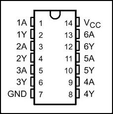
Hex Inverter 7404: the main function of the inverter is to give the complemented output for its input i.e. it will give output which is opposite to input. For example, if the input is low to the inverter, then the output will be high. Just like the normal inverter which gives high output when the input is low and gives low output when the input is high. 7404 IC will be having six independent inverters; Operating supply voltage is around 4.75V minimum to 5.5V maximum, normal supply voltage is 5V. They are used in different applications like inverting buffers, drivers, hex inverters etc. 7404 IC will be available in different packages like DIP (dual inline package), QFP (Quad Flat Package) etc. The pin configuration of Hex Inverter 7404 is shown below.
Inverter Pin Configuration

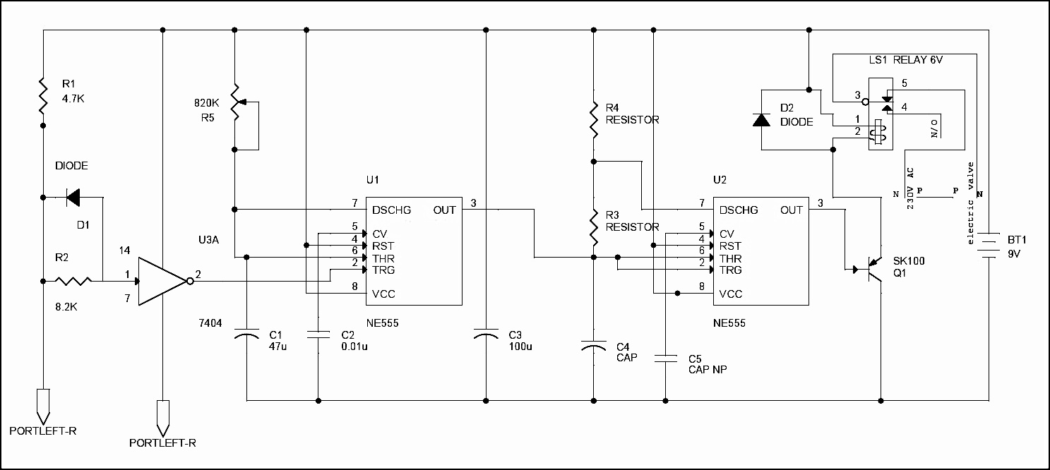
Circuit Diagram of Automatic Plant Irrigation System:

Circuit Diagram of Electronic Watering Plant System
Circuit Explanation:
  • We are all well aware that the plants will die due to lack of water in the soil. Soil will have high resistance when it is dry and it will have very low resistance when soil is wet. We use this simple logic to water the plants and make the circuit work.
  • Two probes which are connected to the circuit are placed into the soil. The two probes will conduct only when soil is wet (resistance is low) and they cannot conduct when soil is dry due to high resistance. The voltage is given to the probes to conduct is given from the battery connected to the circuit.
  • When the soil is dry it will produce large voltage drop due to high resistance. This is sensed by 7404 hex inverter and makes the first NE555 timer trigger which is configured as monostable multivibrator with the help of a electrical signal.
  • When the first NE555 is triggered at pin 2, it will generate the output at pin 3 which is given to the input of second NE555 timer. The second 555 timer is configured as astable multivibrator which got triggered by the first 555 timer and will generate the output and drive the relay which is connected to the electrically operated value through the transistor SK100. You can use a heat sink for SK100 transistor if it is dissipating more heat.
  • The output of second NE555 timer will switch on the transistor SK100 which will drive the relay. Relay which is connected to the input of electrical value and output of value is given to the plant plots through the pipe.
  • When transistor has turned on relay, it will open the valve and water is poured on to the plants pot. When the water content in the soil is increased, the resistance in the soil will get decreased and conduction of the probes will get started which will make the 7404 Inverter to stop the triggering of first 555 timer. Ultimately it will stop the electrical valve which is connected to the relay. Variable resistor (R5) and capacitor (C1) are used to adjust the valve when to we want to conduct the probes.
  • The capacitor C5 (0.01uf) is used to ground, the CV pin of second NE555 timer. C3 will remove the AC noise and allow only DC to the remaining circuit. C4 and R3 will constitute to configure the NE555 in astable multivibrator.
Values of the Components in the Circuit:
  • Capacitor (C4) = 10u 16V.
  • Capacitor (C5) = 0.01u.
  • Resistor (R3) = 27K
  • Resistor (R4) = 27K
  • Diode (D1 and D2) = IN4148
  • Relay = 6V, 150 ohms

Water Level Indicator, water level controller circuit

The Water Level Indicator employs a simple mechanism to detect and indicate the water level in an overhead tank or any other water container. The sensing is done by using a set of nine probes which are placed at nine different levels on the tank walls (with probe9 to probe1 placed in increasing order of height, common probe (i.e. a supply carrying probe) is placed at the base of the tank). The level 9 represents the “tank full” condition while level 1 represents the “tank empty” condition.
When the water-level is below the minimum detectable level (MDL), the seven segment displays is arranged to show the digit 1, indicating that the tank is empty, When the water reaches level1 (but is below level2) the connection between the probes gets completed (through the conducting medium – water) and the base voltage of transistor increases. This causes the base-emitter junction of transistor to get forward biased, this switches transistor from cut-off to conduction mode thus PIN (B0) of microcontroller is pulled to ground hence, the corresponding digit displayed by the seven segment display is 2. The similar mechanism applies to the detection of all the other levels. When the tank is full, all inputs to microcontroller become low and all its outputs go high. This causes the display shows a 9 also in this case a buzzer sound is given, thereby indicating a “tank full” condition.
Most water level indicators are equipped to indicate and detect only a single level. The Water Level Indicator implemented here can indicate up to nine such levels and the microcontroller displays the level number on a seven segment display. So, not only is the circuit capable of cautioning a person that the water tank has been filled up to a certain level, it also indicates that the water level has fallen below the minimum detectable level. This circuit is important in appliances such as the water cooler where there is a danger of motor-burnout when there is no water in the radiator used up also it can be used in fuel level indication.

Water Level Indicator Project Features:

  • Easy installation.
  • Low maintenance.
  • Compact elegant design.
  • The Automatic water level controller ensures no overflows or dry running of pump there by saves electricity and water.
  • Avoid seepage of roofs and walls due to overflowing tanks.
  • Fully automatic, saves man power.
  • Consume very little energy, ideal for continuous operation.
  • Automatic water level controller provides you the flexibility to decide for yourself the water levels for operations of pump set.
  • Shows clear indication of water levels in the overhead tank.

Hardware Description:

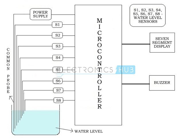
Water Level Indicator Project Block Diagram:

Water Level Indicator Block Diagram
Figure 2.1.1 Block diagram

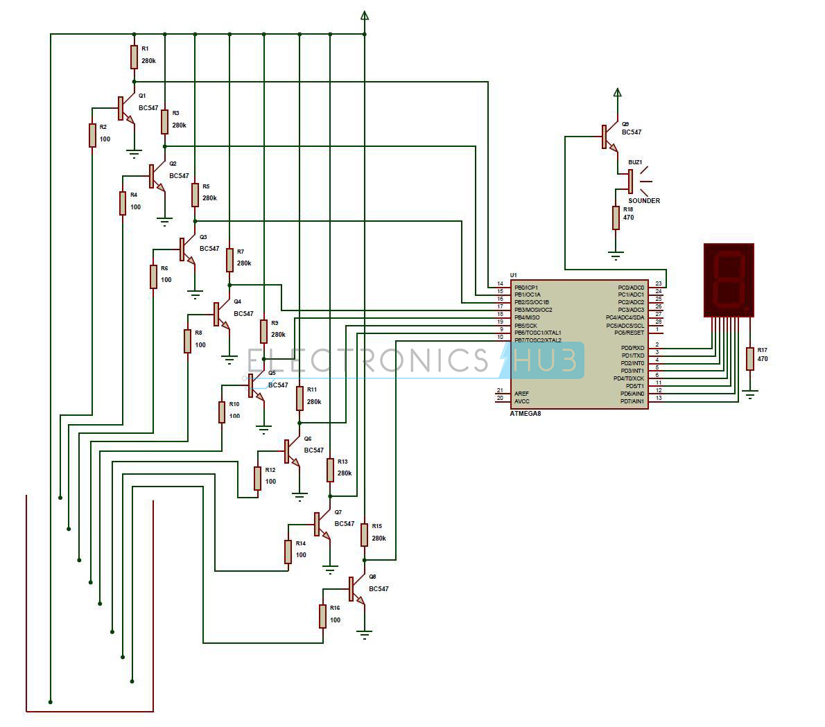
Water Level Indicator Project Circuit Diagram:

Water Level Indicator Schematic Diagram

Water Level Indicator Project Description:

This is the circuit diagram and description for water level indicator.
  • A constant 5v power supply is given to the microcontroller and rest of the circuit from a battery.
  • The tank has 9 conductive type sensors (other types of sensors have been mentioned earlier but in our project only conductive type are used) embedded into it and 8 wires of sensors out of 9 are connected to transistors and the 9th is connected to 5v+ supply.
  • The use of transistor is it acts as inverter (i.e. in on state gives low voltage at output and in non conducting state gives high voltage at its output), all transistors outputs are connected to 1,2,3,4,5,6,7,8 pins (PORTB) of microcontroller.
  • Seven segment display is connected to pin no. 33 to 40 (PORTA). It is connected in common cathode fashion.
    The Output for the 7th level is not only shown in seven segment display but also indicated with a discontinuous buzzer sound.
  • Output for the 8th level (i.e. tank full condition) is not only shown in seven segment display but also indicated with a continuous buzzer sound.

Operation:

The operation of this project is very simple and can be understood easily. In our project “water level indicator” there are 3 main conditions:
  1. There is no water available in the source tank.
  2. Intermediate level i.e. either of 3rd to 7th level.
  3. There is ample amount of water available in the source tank.
So let us discuss on the more about these 3 conditions

CONDITION 1: Water not available

When the tank is empty there is no conductive path between any of the 8 indicating probes and the common probe (which is connected to 5v+ supply) so the transistor base emitter region will not have sufficient biasing voltage hence it remains in cut off region and the output across its collector will be Vc approximately 4.2v. As in this case the microcontroller is used in the active low region (which means it considers 0-2 volts for HIGH and 3-5 volts for LOW) now the output of transistor which is 4.2v approximately will be considered as LOW by the microcontroller and hence the default value given by microcontroller to the seven segment display is 1 which indicates as the tank is empty.

CONDITION 2: Intermediate levels

Now as the water starts filling in the tank a conductive path is established between the sensing probes and the common probe and the corresponding transistors get sufficient biasing at their base, they starts conducting and now the outputs will be Vce (i.e. 1.2v-1.8v) approximately which is given to microcontroller. Here the microcontroller is programmed as a priority encoder which detects the highest priority input and displays corresponding water level in the seven segment display. In this project while the water level reaches the 7th level i.e. last but one level along with display in seven segment a discontinuous buzzer is activated which warns user that tank is going to be full soon.

CONDITION 3: Water full

When the tank becomes full, the top level probe gets the conductive path through water and the corresponding transistor gets into conduction whose output given to microcontroller with this input microcontroller not only displays the level in seven segment display but also activates the continuous buzzer by which user can understand that tank is full and can switch off the motor and save water.

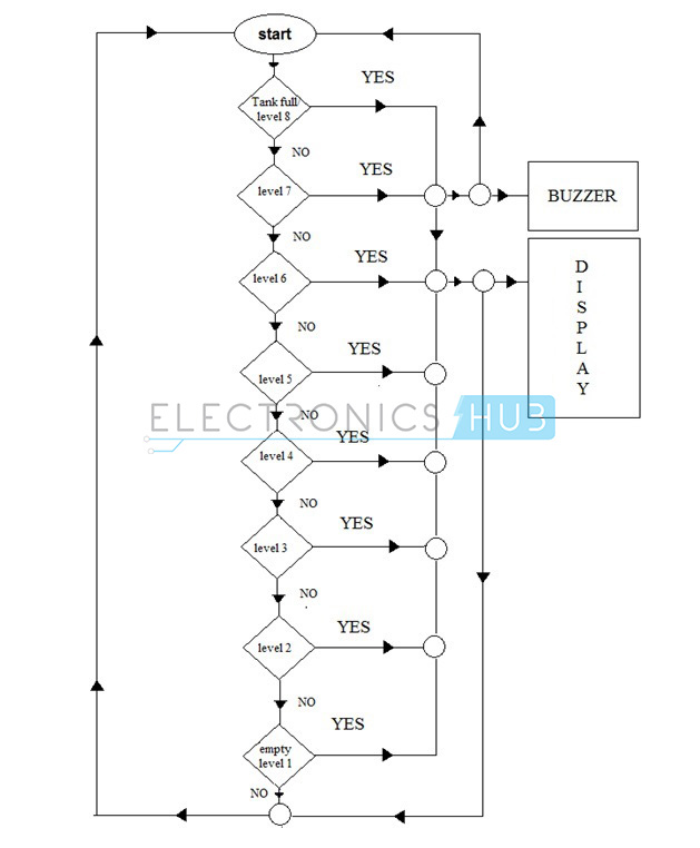
Flow Chart:

Water Level Indicator Flow ChartFigure 4.2.1 Flow chart
Flow chart gives the clear and easy understanding of the project. The process goes on as follows:
The microcontroller checks if the tank is full if the condition is satisfied it indicates the same on display unit and also sounds a buzzer if the condition fails it checks if the tank is filled upto level 7 and this process continues and the corresponding level is indicated in the display unit.

Conclusion and Scope:

Applications of Water Level Indicator:

  • Automatic Water level Controller can be used in Hotels, Factories, Homes Apartments, Commercial Complexes, Drainage, etc., It can be fixed for single phase motor, Single Phase Submersibles, Three Phase motors. (For 3Æ and Single Phase Submersible Starter is necessary) and open well, Bore well and Sump. We can control two motor and two sumps and two overhead tanks by single unit.
  • Automatic water level controller will automatically START the pump set as soon as the water level falls below the predetermined level (usually 1/2 tank) and shall SWITCH OFF the pump set as soon as tank is full.
  • Fuel level indicator in vehicles.
  • Liquid level indicator in the huge containers in the companies.

Schematic of DC Fan Controlled by Temperature Circuit

Fan controlled by temperature circuit 
The circuit exploits the property of Thermistor to operate the DC Fan. Thermistor is a kind of temperature dependent resistor and its resistance varies depending on the temperature in its vicinity. There are two types of Thermistors- NTC and PTC.
Negative temperature coefficient (NTC) Thermistor decreases its resistance when the temperature increases while Positive temperature coefficient (PTC) increases its resistance when the temperature increases. Thermistors are bead like resistors available from 100 ohms to 10K or more values. Here a 4.7K NTC Thermistor is used.IC uA 741 is used as a voltage comparator to switch on the DC fan. Its INV input (pin2) gets an adjustable voltage through VR while its Non-INV (pin3) input gets voltage through a potential divider comprising R1 and the Thermistor. Thus the voltage at pin3 depends on the conductivity of the Thermister.
When the temperature is normal (as set by VR), pin3 gets higher voltage than pin2 and makes the output of IC high as indicated by Red LED. This high output keeps T1 off since its base is positive. DC fan remains off in this condition. When the temperature increases above the value set by VR, resistance of Thermister decreases and the voltage at pin3 decreases. As a result, output of IC becomes low to switch on T1.
A small brush less DC fan (one used in computers) turns on to increase the air circulation. When the temperature returns normal, Fan automatically turns off. Diode 1N4007 is necessary to remove back EMF when T1 turns off.

Cell Phone Detector circuit,

This is a mobile phone sniffer circuit that can detect the signals being used in the GSM (Global System for Mobile Communication) band at about 900 MHz. Since the signals are digitally encoded, it can detect only the signal activity, not the speech or the message contents. A headphone is used to hear the detected signals.

Project Description

The circuit schematic is given in the .rar archive attachment. There are two separate detector units. Every detector unit consists of a dipole antenna, a choke and a diode. The antenna receives the GSM signals in media. Then a small amount of charge is induced in the choke. The diode demodulates the signal and finishes detecting. The diodes must be schottky diodes or germanium diodes. Since the forward voltage of a silisium diode is high, it won’t give a sufficient result in this circuit. LM358 amplifies the received signal. It contains two separate op-amps that are supplied by a common power source. R3 and R7 resistors determine the gain of the amplifiers. When the resistor values are greater than 10M then the noise level increases. If they are small like about 100k, this time it becomes harder to hear the signal.
The PCB file is provided in pdf format. You can apply it to the board by using the ironing method.
R1, R5 : 100K 1/4W Resistor
R2, R6 : 1k 1/4W Resistor
R3, R7 : 8.2M 1/4W Resistor
R4, R8 : 220 Ohm 1/4W Resistor
R9 : 2.2K 1/4W Resistor
D1, D2 : BAT43 Schottky Diode
C1, C2, C4 : 100nF Polyester Capacitor
C3 : 100uF 16V Electrolytic Capacitor
L1, L2 : See Text
U1 : LM358
J1 : 8 Pin Socket
J2 : Stereo JAck
1 × 9V Battery
1 × 9V Battery Socket
1 x LED
1 x On/Off Switch
Figure:1

Figure 1 

The diodes, gain of the amplifiers and the length of the antenna is critical in this circuit. Calculating the length of the antenna is simple. The formulation is given below.
λ=c/f = (300.000km/h)/900MHz =33.3 cm Then; Antenna Length = λ / 2 = 16.6 cm
So there are four pieces of antenna and each one is about 8.3 cm long. The wire type is not critical but its better to choose a fairly thick wire that will not bend too easily. It is a 1.5 mm diameter wire seen in the photo that we used. The two antennas must be positioned perpendicularly.
Figure:2

Figure 2 

The chokes are 10 turn molded chokes. The wire diameter should be about 0.5 – 06 mm and wound around a 5 mm cylindrical object.
Diodes are very critical. You should use one of BAT43, BAT45, AA112, AA116 or AA119. When a silisium diode is used the circuit also works but the detecting area becomes very very narrow.