1. FASTEST-FINGER-FIRST USING 89C51
2. MICRO PROCESSOR BASED REVERSIBLE D.C. MOTOR CONTROL
3. MOVING MESSAGE DISPLAY 8085 MICROPROCESSOR
4. PC16F84- BASED CODED DEVICE SWITCHING SYSTEM
5. STEPPER MOTOR CONTROL USING 89C51
6. MIC-89C51 MONITORING SYSTEM
7. MANUAL AT 89C51 PROGRAM
8. AT 89C2051 BASED COUNTDOWN TIMER
9. MICROCONTROLLER BASED CODE LOCK USING AT 89C2051
10. LCD FREQUENCY METER USING 89C2051
11. CALLER ID UNIT USING MICRO-CONTROLLER
12. PIC 18 F 84 MICRO-CONTROLLER BASE CODE DEVICE SWITCH SYSTEM
13. MICROPROCESSOR-BASED HOME SECURITY SYSTEM
14. STEPPER MOTOR CONTROL USING 89C51 MICRO-CONTROLLER
15. MICRO CONTROLLER BASED TEMPERATURE METER
16. MICRO CONTROLLER BASED HEARTBEAT MONITOR
17. RS232 ANOLOG TO DIGITAL CONVERTER USING AT89C51 MCU
18. ULTRASONICRANGEFINDER USING PIC MICRO CONTROLLER
19. CALLER- ID UNIT USING MICRO CONTROLLER
20. MICRO CONTROLLER BASED PATHFINDER
21. MICRO CONTROLLER BASED ROBOT.
22. MICRO CONTROLLER MOVING MESSAGE DISPLAY
23. MICRO CONTROLLER BASED RELAY SWITCHING
24. MICRO CONTROLLER AUTO DIALER USING GSM.
25. MICRO CONTROLLER BASED WATER LEVER INDICATOR
26. MICRO CONTROLLER BASED WIRELESS HOME AUTOMATION
27. MICROCONTROLLER BASED RADAR SYSTEM
28. MULTI CHANNEL INFRA RED CONTROL 4 different point 89c2051 micro controller in transmitter and receiver, using infra red technique.
29. MOVING MESSAGE DISPLAY : 89c51 micro controller Led matrix,
30. Digital clock with alarm: using 89c51 micro controller
31. TRAFFIC LIGHT WITH DOWN COUNTER : all the four sides of the road with one side counter display using 89c51 micro controller circuit.
32. ULTRASONIC DISTANCE METER USING MICROCONTROLLER
33. PRI-PAID CAR PARKING SYSTEM
34. MULTILEVEL CAR PARKING BY MCU
35. MICRO CONTROLLER TEMPERATUIRE METER
36. ANOLOG TO DIGITAL CONERTER USING AT89C51 MCU
37. INFARED REMOTE CONTROLE SYSTEM
38. ULTRASONIC MOVEMENT DETECTOR
39. MICROCONTROLLER BASED TACHOMETER
40. MCU BASED VISITOR COUNTER
41. PWM CONTROL OF DC MOTOR USING 89C51
42. AN INTELLIGENT AMBULANCE CAR WHICH CONTROL TO TRAFFIC LIGHT
43. PRE-PAID ENERGY METER
44. MICROC CONTROLLER BASED LINE FOLLOWER OR TRACING ROBOT
45. AUTOMATED WALKING ROBOT CONTROLLED BY MCU
46. AUTO BRAKING SYSTEM
47. AUTOMATIC RAILWAY CROSSING GATE CONTROLLER
AddThis
Showing posts with label microcontroller based project. Show all posts
Showing posts with label microcontroller based project. Show all posts
Friday, 21 May 2010
Microcontroller Based Projects list
Three phase Induction motor Control Using Microcontroller
* Multi Task Industrial Timer Using Microcontroller* Multi Task Industrial Timer Using Microcontroller
* Digital Clock Using AT89C2051 Microcontroller
* Laser Based Automatic Visitor Counter cum Room Light Controller
* Biomedical Data Transmission Using Wireless Network
* Digital Clock Using AT89C51 Microcontroller
* Industrial Automation using computer’s parallel port (Visual Basic)
* Digital Day And Date Display Using Microcontroller
* Digital Countdown Timer Using Microcontroller
* Digital 74 Series IC Tester
* Digital Visitor Counter Using Microcontroller
* DS1620 Based Temperature Controller Using Microcontroller
* DS1820 Based High Precision Temperature Indicator Using Microcontroller
* Electronic Voting Machine Using Microcontroller
* Electronics Components Tester Using Microcontroller
* Biometric Security System (Finger Print Based)
* Ultrasonic Distance Meter using microcontroller
* Mobile Controlled Robot Machine
* Telephone Controlled Device Switching Using Microcontroller
* Infrared Interrupt counters Using Microcontroller
* 6 Line and one fan Infrared Remote Switch Using Microcontroller
* Infrared Remote Switch Using Microcontroller
* Interactive Voice Response System (IVRS)
* Line Following Robot Using Microcontroller
* Microcontroller Based Telephone Caller ID
* Microcontroller Based Digital Clock with Alarm
* Password Based Digital code Lock Using Microcontroller
* Multi function Running Lights Using Microcontroller
* Parallel Telephone instrument with secured privacy Using Microcontroller
* Computer to microcontroller communication (Wireless) Using Microcontroller
* PC BASED DATA LOGGER Using Microcontroller and Visual Basic
* Computer Based Digital IC Tester
* GPS
* PC Controlled Robot Machine
* Control Ur PC by remote Control
* Simcard Based Prepaid Energy Meter Using Microcontroller
* Industrial Automation and message transmission using internet
* Digital Clock with Remote controlled time settings Using Microcontroller
* Electric Energy Meter Reading Through Wireless
* Wireless Controlled Robot Machine
* RFID Based Attendance System
* RFID Based Security System
* Data Transmission Through wireless network
* Sending SMS To Landline Telephone Using Microcontroller
* Wireless Data Communication (AT89S52)
* Efficient Solar Energy generation using movable solar panel
* Motor controller using Telephone
* Industrial control using Telephone
* Temperature controlled Colling Fan Using Microcontroller
* Time Operated Electrical Appliances Controlling System
* Traffic signal Controller Using Microcontroller
* Two Line Intercom Using Microcontroller
* Microcontroller-based LED Light Chaser
* Microcontroller-based Temperature Indicator
* PC-based Wireless Stepper Motor Control
* Microcontroller-based Ring Tone Player
* Solar LED Lighting System
* Clap-operated Appliance Control
* Microcontroller-based Speedometer-Cum-Odometer
* PC-Based Mobile Robot for Navigation
* Solar Electric Fence
* Four-Channel Analogue-to-Digital Converter
* Microcontroller-based Temperature Meter
* Kapalbhati Pranayama Timer
* Microcontroller-Based Inductance Meter
* Cellphone-Operated Land Rover
* Presentable Timer Using Secret-Coded Punched Card
* Rank Display System for Race and Quiz Competitions
* Remote-Controlled Toy Boat
* Microcontroller-Based Heart-Rate Meter
* Multiple Devices Switching Through Parallel Port
* Microcontroller-Based Capacitance Meter
* Token Number Display
* Microcontroller-Based DC Motor Speed Controller
* MICROCONTROLLER-BASED TEMPERATURE INDICATOR
* Buzzer Controller for 8-Team Quiz Contests
* Microcontroller-based Ultrasonic Distance Meter
* Microcontroller-based Tachometer
* Temperature Indicator-cum-Controller
* Microcontroller-Based Alarm Clock
* Simple PC-Based Digital Sound-Level Meter
* Low-Cost Versatile Timer Using AT89C2051
* Parallel-Port Interfacing and Programming Aid
* Digital Heart-Beat Counter
* Secured Room Access System
* Digital Voltmeter
* Microcontroller-based Graphics Display
* Microcontroller-based Industrial Timer
* Standalone Digital Clock
* PC-based Dual DC Motor Controller
* Wireless Messaging Via Mobile/Landline Phone
* Microcontroller-based Infrared Tracking Robot
* Remote-Controlled Real-Time Clock with Device Controller
* Auto Controller for Petrol-Run Power Generator
* Design Your Own Infrared Remote
* PIC16F84-based Digital Thermometer
* Water-level Controller-cum-motor Protector
* Digital Phase Selector
* Microcontroller-based Bidirectional Visitor Counter
* Microcontroller-based Automatic Flush System
* Two-Channel PC-based Oscilloscope
* Quiz Buzzer
* Stepper Motor Controller Using AT89C51
* Beverage Vending Machine Controller
* Digital Thermometer-cum-Controller
* Digital Weight Accumulator
* Remotely Programmable RTC-Interfaced Microcontroller for Multiple Device Control
* Auto Switch for TV
* Microcontroller-based Code Lock
* Microcontroller-based Triggering Circuit for SCR Phase Control
* Parallel-Port Testing and Programming Aid
* Fastest-Finger-First Using Microcontroller
* Remote-Controlled Land Rover—A DIY Robotic Project
* 3D Surround Sound System
* AVR Microcontroller-Based Clock
* Automatic Rain Timer
* Power Factor Correction
* AT89C2051-Based Countdown Timer
* PC-Based Remote-Controlled Stepper Motor
* Low-Cost LCD Frequency Meter
* PC-Based Transistor-Lead Identifier
* A Simple Directional Detector/Counter
* Using AVR Microcontroller for Projects—Part 3 of 3
* Speed Checker for Highways (2005)
* Using AVR Microcontroller for Projects—Part 2 of 3
* Automatic 3-Phase Induction Motor Starter
* Using AVR Microcontrollers for Projects—Part 1 of 3
* Noise-Muting FM Receiver
* Digital Stopwatch
* Remote-Controlled Stepper Motor
* Computerized Electrical Equipment Control
* Manual AT89C51 Programmer
* Medium-Power Low-Cost Inverter
* Programmable Timer Based on AT90S4433 AVR
* Low-Cost Energy Meter Using ADE7757
* Two-Wheeler Security System
* Auto Changeover to Generator on Mains Failure—Part II
* PC-based Scrolling Message Display
* Auto Changeover to Generator on Mains Failure—Part I
* Device Control through PC’s Parallel Port Using Visual Basic
* Remote-Controlled Digital Audio Processor
* Microcontroller-based Real-time Clock
* Standalone Scrolling Display Using AT90S8515 AVR
* Moving Message Over Dot-Matrix Display(2004)
* Ultrasonic Lamp-Brightness Controller
* Digital Combination Lock
* Safety Guard for the Blind
* Microprocessor-Based Home Security System
* Stepper Motor Control Using 89C51 Microcontroller
* Dynamic Temperature Indicator and Controller
* Voice Recording and Playback Using APR9600 Chip
* Load Protector with Remote Switching Facility
* PIC16F84-Based Coded Device Switching System
* Remote-Controlled Sophisticated Electronic Code Lock
* Temperature Indicator Using AT89C52
* Device Switching Using Password
* Laser-Based Communication Link
* Programmer for 89C51/89C52/89C2051 Microcontrollers
* A Bidirectional Visitors Counter
* Digital Clock Using Discrete ICs
* Lift Overload Prevented
* Sound-Operated On/Off Switch
* Digital Water-Level Indicator Cum Pump Controller
* PC-Based Data Logger
* Automatic Water-Level Controller
* Microcontroller-Based Call Indicator
* Controlling a 7-Segment Display Using PC’s Parallel Port(2003)
* Economical UPS for Cordless Phones
* Binary-To-Hexadecimal Decoder
* Proportional Load Control Using PC
* Multifactor Emergency Light
* Fluid Level with Indicator
* Microcontroller-Based School Timer
* Telephone Remote Control
* Auto-Control for 3-Phase Motors
* Programmable Melody Generator -Part II
Microcontroller Based Projects
- WIRELESS MESSAGING VIA MOBILE/LANDLINE
- GSM BASE HOME SECUIRTY SYSTEM
- GSM BASED HOMEAUTOMATION & SECUIRTY
- AUTOMATIC TOLL TAX
- VOTING MACHINE
- SMS BASE DEVICE SWITCH
- SOLAR TARKER SYSTEM
- TEXT DATA COMMUNICATION THROUGH FIBER/LAGER
- DIGITAL COMBINETION LOCK
- SAFETY GUARD FOR THE BLIND (PROXIMITY BASE
- SMS THROUGH TELEPHONE
- SPEED CHECKER FOR HIGHWAYS
- SMART CARD
- DATA SECUIRTY SYSTEM
- TOUCH SCREEN
- HEART BEAT MONITOR
- AUTOMATIC ROOM LIGHT CONTROLLER:
- RADAR SYSTEM ILIGAL AROPLAN DETECTOR
- PRI-PAID CAR PARKING
- MULI LAVEL CAR PARKING
- FASTEST-FINGER-FIRST USING 89C51
- MICRO PROCESSOR BASED REVERSIBLE D.C. MOTOR CONTROL
- STEPPER MOTOR CONTROL USING 89C51
- MIC-89C51 MONITORING SYSTEM
- MANUAL AT 89C51 PROGRAM
- AT 89C2051 BASED COUNTDOWN TIMER
- MICROCONTROLLER BASED CODE LOCK USING AT 89C2051
- LCD FREQUENCY METER USING 89C2051
- CALLER ID UNIT USING MICRO-CONTROLLER
- MICROPROCESSOR-BASED HOME SECURITY SYSTEM
- STEPPER MOTOR CONTROL USING 89C51 MICRO-CONTROLLER
- MICRO CONTROLLER BASED TEMPERATURE METER
- MICRO CONTROLLER BASED HEARTBEAT MONITOR
- ULTRASONICRANGEFINDER USING PIC MICRO CONTROLLER
- CALLER- ID UNIT USING MICRO CONTROLLER
- MICRO CONTROLLER BASED PATHFINDER
- MICRO CONTROLLER BASED ROBOT.
- MICRO CONTROLLER MOVING MESSAGE DISPLAY
- MICRO CONTROLLER BASED RELAY SWITCHING
- MICRO CONTROLLER AUTO DIALER USING GSM.
- MICRO CONTROLLER BASED WATER LEVER INDICATOR
- MICRO CONTROLLER BASED WIRELESS HOME AUTOMATION
- MICROCONTROLLER BASED RADAR SYSTEM
- MULTI CHANNEL INFRA RED CONTROL 4 different point 89c2051 micro controller in transmitter and receiver, using infra red technique.
- MOVING MESSAGE DISPLAY : 89c51 micro controller Led matrix,
- Digital clock with alarm: using 89c51 micro controller
- TRAFFIC LIGHT WITH DOWN COUNTER : all the four sides of the road with one side counter display using 89c51 micro controller circuit.
- ULTRASONIC DISTANCE METER USING MICROCONTROLLER
- PRI-PAID CAR PARKING SYSTEM
- MICRO CONTROLLER TEMPERATUIRE METER
- ANOLOG TO DIGITAL CONERTER USING AT89C51 MCU
- INFARED REMOTE CONTROLE SYSTEM
- ULTRASONIC MOVEMENT DETECTOR
- MICROCONTROLLER BASED TACHOMETER
- MCU BASED VISITOR COUNTER
- PWM CONTROL OF DC MOTOR USING 89C51
- AN INTELLIGENT AMBULANCE CAR WHICH CONTROL TO TRAFFIC LIGHT
- PRE-PAID ENERGY METER
- MICROC CONTROLLER BASED LINE FOLLOWER OR TRACING ROBOT
- AUTOMATED WALKING ROBOT CONTROLLED BY MCU
- AUTO BRAKING SYSTEM
- AUTOMATIC RAILWAY CROSSING GATE CONTROLLER
- CELL PHONE OPERATED LAND ROVER PROJECT
Tuesday, 11 May 2010
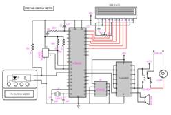
PREPAID ENERGY METER
A scheme of Electricity billing system called “PREPAID ENERGY METER WITH TARIFF INDICATOR” can facilitate in improved cash flow management in energy utilities and can reduces problem associated with billing consumer living in isolated area and reduces deployment of manpower for taking meter readings. Every consumer can buy a memory card (is nothing but an EEPROM IC) with a password stored inside it using a MC program. The memory card is available at various ranges (ie. Rs 50, Rs 100, Rs 200 etc…).In our project we have given the name for memory card as smart card. When the consumer insert a smart card into the card reader which is connected in “prepaid energy meter with tariff indicator”kit.Then the card reader will read the stored information and delete the information from the EEPROM IC(smart card) using the MC program. So that the smart card cannot be reused by others. Suppose if a consumer buy a card for Rs.50/- he / she can insert this amount through the card reader so that prepaid energy meter with tariff indicator kit will be activated. According to the power consumption the amount will be reduced. When the amount is over, the relay will automatically shutdown the whole system. In our project we also have a provision to give an alarm sound to consumer before the whole amount is reduced.
Friday, 23 April 2010
AT90LS8515 Digital Message Machine


Introduction
For my final design project I decided to design and build a digital dot matrix message device. I've seen devices similar to this before and I wanted to find out if I could build one myself. The display consists of 7 LEDs in a vertical row. By moving them fast enough back and forth over each other, I can display a message which appears to be generated by a 7*n matrix of LEDs and not a single column of LEDs.
High Level Design
My first thoughts on this project focused on the most important aspect of the project which was to get the LEDs moving fast enough and refreshing often enough for the message to be perceived as a constant display with the LEDs moving. I knew the microcontroller was fast enough, and I hoped that the LEDs could turn on and off fast enough. The major hurdle I faced was how to actuate the LEDs. My first choice was a wand that oscillated back and forth. However, when the idea of creating a spinning disc was offered, I jumped on it. I could create a disc out of aluminum and mount all of my electronics on it. The device would be completely stand-alone (which is cool) and it would be easy to spin it at a fast enough rate to meet the hardware requirements. After that, it was merely a matter of writing my code to turn the lights on and off.
Hardware Design
The hardware portion of this project presented as much of a challenge as the software portion. Once I decided on using a disc to spin the LEDs, I needed to figure out how to manufacture this disc. I decided to go with aluminum, since Upson has a metal shop and my roommate is a Mechanical Engineer who could help me out with the machining. One thing that is vital to the success of this project was the ability to spin the LEDs at a fast and smooth rate. If the disc were to wobble, it would significantly degrade the performance of the display. I choose aluminum as my material since it could be machined easily and in such a way that it was precise enough to rotate smoothly.
After talking to my roommate, the guys in the machine shop and a few others, I came up with some preliminary drawings that turned out to be relatively close to the final product.


I knew I needed a way to mount the rod and disc when it was finished so I decided to use Roller Blade bearings to mount the rod. I choose and appropriate sized rod and a disc which was 3/4" thick and 6" in diameter and I was off and running. The machining took so much longer than I anticipated. This project never would have made it to fruition without the tireless help of my roommate Greg Gombert who helped me machine the disc, which I could have never done alone. The specs show the basic design for the disc. We drilled a hole down the center for mounting the disc on the rod. We attempted to machine down the disc so the thickness was much less than 3/4" everywhere but the center, but I soon realized that this would take hours, and a couple hours of machine time is close to a day real time.
After we got the hold down the center, we needed a way to attach the disc to the rod. To do this, we made two aluminum collars. We machined collars that could be attached to the rod on either side of the disc, and then made it so that the two collars attached to the disc. After that, I built a wooden stand to hold the bearings that would support the rod and I had a spinning disc on a rod. Doesn't sound like much, but it took long enough to build.
Electronic Hardware Design
The electronic hardware design for this project was relatively straightforward. The microcontroller is very easy to make stand alone, requiring power, ground and the oscillator. The LEDs were very easy to design, requiring only a 1k RPac with one end connected to Vcc and the other end of the LEDs to PortB. The Sensor used had an LED on one side and a phototransistor on the other. I mounted this on the disc 90 degrees from the LEDs. When the LEDs were at 180 degrees and the LEDs were at 90 degrees, the plane of the photodetector was broken and a signal was read on PortC[0]. This allowed me to measure the period and to use this for the timing for the rest of the design. The only other electronic components were the battery and the regulator. A 9V battery was used for a power supply and a 5V regulator provided the necessary voltage level for the rest of the circuit. A simple switch allowed me to control conductivity between the battery and the regulator.

Software Design
There were two things necessary to getting the project working.
- Getting the right data out of PortB to the LEDs
- Sending that data out at the right time.
The timing worked out better than I thought it would. I had a double precision variable store the time it took for each revolution and then used that value to calculate all my timing. This means that all the timing is based on the period for the previous cycle and not the current cycle, but since they are so close, it doesn't matter and is entirely sufficient for this application. A double precision variable counting 8uSec ticks allows me to measure periods up to a little over .5sec. Since the disc needs to rotate much faster than this to display a message, this is good range for the period. By shifting this value right by one bit, I have half the period and can easily determine when the LEDs move from 90 degrees to 270 degrees. So I can start displaying the message after half the period has gone by and I can shut them off when the sensor goes off. This easily took care of the first part of the timing requirement.
After I got this first part out of the way and debugged it, I got the disc to display messages. However, as the disc slowed down, the message started moving more and more left (since the number of uSec after the wand hit 270 degrees was a constant.) Also, the length of time between displaying portions of the letter was constant, so the width of the letters continually got smaller. If only I could obtain a value which would allow me to calculate the time after 270 degrees to start displaying and to calculate a value for display spacing so the message would stay in place. Wait, the period! :) I basically used the period and shifted it right or left until I got a value that was appropriate for the spacing between wand displays. I didn't have a specific timing requirement for exactly how long to wait between sending out the rastorization portions of the letters. I could get the data fast enough, it was just a matter of waiting to send it out. So I just played with the factors until I got one that looked good. If the letters were too wide, shift the variable right. If they were too narrow, shift it left.
Appendix
Thursday, 22 April 2010
Laser Audio Transmitter
Introduction
Project Details
Rationale
Inspiration for this project came from a design in the book “Gonzo Gizmos: Projects & Devices to Channel Your Inner Geek,” a book written by Simon Quellen Field, in which a laser/solar cell combination allowed for the transmission of an audio signal using light. A topic of research at MIT Lincoln Laboratory inspired us to incorporate tracking capability while keeping the project budget affordable at a hobbyist level.
Logical Structure
Our project is divided into two distinct sections: audio transmission via hardware, and alignment control via software. The former can be accomplished once the latter has succeeded, making the two tasks mutually dependent for overall functionality. The alignment is accomplished using a servo motor to rotate the transmitter until it aligns with the receiver. This is done by detecting the light emitted from the receiver’s laser using a phototransistor. The transmitter scans over its free range until it finds the receiver, at which point the transmitting laser is turned on and the audio signal is picked up by an array of photodiodes. The details of this process are explored below.
Safety and Standards
Since we are using lasers, the effects of exposure need to be considered. The lasers we used were purchased commercially, and comply with class IIIA power and safety specifications, as designated by the ANSI Z136.1 consensus. In the US, ANSI and OHSA standards specify the parameters under which lasers can be safely operated. For a class IIIA laser, the beams are generally not hazardous without the use of focusing equipment, though direct exposure to the eye should be avoided. With this in mind, we operated the device in a plane that lacked reflective objects and was well below eye level. Additionally, the transmitting laser is turned off when the exact direction of the laser is not known (i.e. when the transmitter is scanning the area). The receiver’s laser is limited to be just bright enough to be detected by the transmitter, but not at the peak amplitude.
Hardware/Software Tradeoffs
The audio signal sent by the transmitter is provided externally rather than via the microcontroller, since external devices represent more flexibility and mobility in the information that can be sent. Having the audio synthesized by the Mega644 would require some form of external memory and a method of flashing from an external source anyways, so we decided to cut out the middleman.
The audio signal is sent via an analog transmission instead of decoding it into a digital signal. Optical transmission is usually done using with digital signals, requiring hardware for decoding at the receiver end. By transmitting the analog audio signal through laser amplitude modulation, we cut down on the transmitter and receiver hardware by eliminating the need for encoding and decoding processors.
Design Details
Hardware
Transmitter

Subscribe to:
Posts (Atom)

