AddThis

Bookmark and Share

Sunday 29 April 2012

Railway Switches And Signals

Signals, including those used for communication between occupants of a car or train.Indicators, recorders, telegraphic, telephonic, or other similar apparatus when especially designed for use in connection with car or train movements, except manually-set devices, such as train and engine signs and markers capable of general use.

Devices on the roadway, such as signals, switches, circuit closures, gates, etc., actuated or controlled from or by the moving vehicles, except circuit-controllers actuated by the vehicle for the purpose of energizing sectionalized conductors used for supplying propulsion-current thereto.

Automatic train stop and speed control means, the actuation of which is initiated by agencies not on the train or by wheel derailment or defects in train structure and mechanism, the automatic stop, for classification purposes, being considered an equivalent of and substitute for a railway signal; but train stopping and control mechanism cooperating with obstacles fixed in position upon the track which have no moving parts are excluded from this class except when they cooperate with speed-responsive devices on the train.

Safety devices, including derailing switches and blocks, used for preventing accidents caused by the misplacement of switches, disregard of signals etc.The structure of signals, switches, frogs, and crossings and their appurtenances.Mechanism for the manual or other actuation of any of the devices of the class.

Remote Vehicle With Unlimited Range

In this project, the robot is controlled by the mobile phone that makes a call to the mobile phone attached to the robot .In the course of a call, if any button is pressed; a tone corresponding to the button pressed is heared at the other end of the call. This tone is called ‘dual tone-multiple-frequency' (DTMF) tone .The robot perceives the DTMF tone with the help of the phone stacked in the robot.

The received tone is processed by the ATmega16 microcontroller with the help of DTMF decoder MT8870.The decoder decodes the DTMF tone into its equivalent binary digit and this binary number is sent to the microcontroller. The microcontroller is programmed to take a decision for any given input and outputs its decision to motor drivers in order to drive the motor for forward or backward motion or a turn.

The mobile that makes a call to the mobile stacked in the robot as a remote. So this simple robotic project does not require the construction of receiver and transmitter units. DTMF signaling is used for telephone signaling over the line in voice-frequency band to the call switching center. The version of DTMF used for telephone tone dialing is known as ‘Touch Tone'. DTMF assigns a specific frequency (consisting of two separate tones) to each key so that it can easily be identified by the electronics circuit. The signal generated by the DTMF encoder is a direct algebraic summation, in real time, of the amplitude of two sine (cosine) waves of different frequency, i.e., pressing ‘5' will send a tone made by adding 1336Hz and 770Hz to the other end of end of the line .The tones and assignment in a DTMF system are shown in table I.

CIRCUIT DESCRIPTION:

The important components of this rover are a DTMF decoder, microcontroller and motor driver. An MT8870 series DTMF decoder is used here. All types of the MT8870 series use digital counting techniques to detect and decode all the 16DTMF tone pairs into 4-bit code output. The built in dial tone rejection circuit eliminates the need for pre-filtering. When the input signal given at pin 2(IN-) in single-ended input configuration is recognised to be effective, the correct 4-bit decode signal of the DTMF tone is transferred to Q1 (PIN11) through Q4 (PIN14) outputs.

The ATmega16 is a low power ,8-bit ,CMOS microcontroller based on AVR enhanced RISC architecture .It provides the following features:16kb of in-system programmable flash program memory with read-while-write capabilities ,512 bytes of EEPROM ,1kb SRAM,32 general purpose I/O lines and 32 general purpose working registers. All the 32 registers are directly connected to arithmetic logic unit ,allowing two independent register to be accessed in one single instruction executed in one clock cycle .The resulting architecture is more code-efficient.

Output from port pins PD0 through PD3 and PD7 of the microcontroller are fed to inputs IN1 through UN4 and enable pins (EN1 and EN2) of motor driver L293D, respectively, to drive two geared dc motor. Switch S1 is used for manual reset. The microcontroller output is not sufficient to drive the DC motors, so current driver are required for motor rotation.

The land rover can be further improved to serve specific purpose .It require four controls to roam around .The remaining eight controls can be configured to serve other purposes, with some modification in the source program of the microcontroller.

Automated Step Climber

Human body is perfect combination of motion, balance, co-ordination and reflex. It because human brain is so much developed that all these activities can take place in such perfect co-ordination. With advancement in science we humans have created many beautiful creations and robot happens to be one of them. Humans have developed robots that can mimic humans. In the same context it is our humble effort to develop an electro-mechanical autonomous robotic vehicle that can have multiple degree of freedom, which enable it to move through various terrains.

Taking inspiration from NASA’s path finder robot we have tried to make a tone down prototype which control its movement with help of microcontroller which properly co-ordinate its motion. In our project we have tried to built an electro-mechanical autonomous robotic vehicle, which moves over the hurdles in front of it by sensing obstacle with help of sensing circuit and taking controlled action with microcontroller ,which drives the motors to make robot climb over the obstruction.

We have used many other chips to achieve this motion which we have described in the component section. This robotic vehicle could become a prototype for surveillance vehicle and other military vehicles used for detection and detonation of mines .Since cost of this prototype is very less thus it could be inducted in army easily and be made indigenously.Mainly ou project is based on working of microcontroller for the automatic management and motors for hardware management.

At initial position all the wheels are on the ground and microcontroller is programmed in such a way that the robo moves forward till the sensor circuit detect any obstruction. The sensor circuit consist of IR LED and phototransistor .The IR LED emits the IR radiations ,when there no obstruction the phototransistor does not detect any reflected radiation and the vehicle moves forward without any vertical motion.

When any obstruction comes in front of sensor mounted in front of wheel one the IR radiation are reflected back from the obstruction which is picked up by phototransistor .This phototransistor supplies a trigger signal to the comparator which conditions the signal and supplies the signal to microcontroller. The forward motion of the robo stops and microcontroller then detect the signal on a programmed pin. According to programming controller send the signal to the motor driver .

The motor driver drives the rack and pinion which lifts the wheel set one from the ground. The phototransistor detect the radiated IR radiations till the IR LED moves above the obstacle. As the wheels thus IR LED moves above the obstruction no sensor detect any signal thus forward motion of robo is initiated by the controller. Now the second detector detect the obstruction and same action is repeated as in case of first sensor. Once the second wheel moves over the obstruction the center of gravity moves in such a position that robo cannot topple. Thus in similar way third and last wheel climb over the obstruction and the robo moves above the obstruction.


Ultrasonic Based Distance Measurement System

The report details the implementation of distance measurement system using the ultrasonic waves. As the human ear’s audible perception range is 20 Hz to 20 kHz, it is insensitive to ultrasonic waves, and hence the ultrasound waves can be used for applications in industries/vehicles without hindering human activity. They are widely used as range meters and proximity detectors in industries also it can be used in parking assistance system. The distance can be measured using pulse echo and phase measurement method. Here the pulse echo method is used. The measurement unit uses a continuous signal in the transmission frequency range of ultrasonic transducers. The signal is transmitted by an ultrasonic transducer, reflected by an obstacle and received by another transducer where the signal is detected. The time delay of the transmitted and the received signal corresponds to the distance between the system and the obstacle.

The techniques of distance measurement using ultrasonic in air include continuous wave and pulse echo technique. In the pulse echo method, a burst of pulses is sent through the transmission medium and is reflected by an object kept at specified distance. The time taken for the pulse to propagate from transmitter to receiver is proportional to the distance of object. For
contact less measurement of distance, the device has to rely on the target to reflect the pulse back to itself. The target needs to have a proper orientation that is it needs to be perpendicular to the direction of propagation of the pulses. The amlitude of the received signal gets significantly attenuated and is a function of nature of the medium and the distance between the transmitter and target. The pulse echo or time-of-flight method of range measurement is subject to high levels of signal attenuation when used in an air medium, thus limiting its distance range.

Design procedure

The circuit has been divided into two divisions.
(i) Digital section- micro controller and LCD display unit with 5volt power supply
(ii) Analog section –
(a) Transmitting side - Ultrasonic transducers, gain amplifier using uA741 CD4066
CMOS analog switch.
(b) Receiving side - TL084 comparator, gain amplifier, voltage limiter.
(c) +15V and -15V power supply.

The time of flight method is used for finding the distance between the transmitter and the object. The transmitter sends out a burst of pulses and a receiver detects the reflected echo. The time delay between the corresponding edges of the transmitted and received pulses is measured by microcontroller, this gives the time of flight. Substituting the time delay and the velocity of ultrasound in air (330 metres/second) in the following formula we can determine the distance between the transmitter and the target. Fig.2 shows the transmitted and received pulses.

Distance = Velocity X Elapsed time

Electronics Seminar Topics List

1. Quadrics network
2. Worldwide Inter operatibility for Microwave Access
3. Fpga offloads dsp?s.
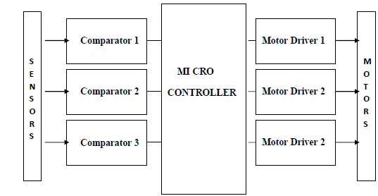
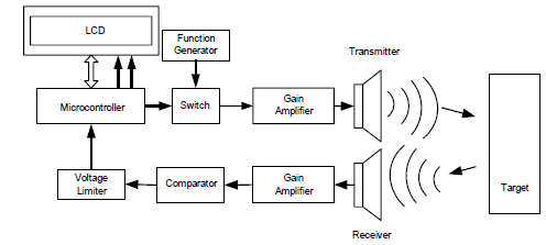
4. Real-Time Obstacle Avoidance
5. Light emitting polymers
6. E-Commerce
7. Extreme ultraviolet lithography*
8. Low Power UART Design for Serial Data Communication
9. Multi threading microprocessors
10. Passive Millimeter-Wave
11. Magnetic Resonance Imaging
12. Microelectronic Pills~
13. Multisensor Fusion and Integration
14. Molecular Electronics
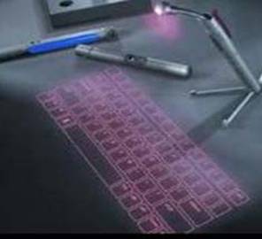
15. Money Pad, The Future Wallet
16. Treating Cardiac Disease With Catheter-Based Tissue Heating
17. Adaptive Multipath Detection4
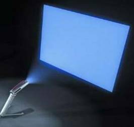
18. Heliodisplay
19. Virtual Reality~
20. Real Time System Interface
21. Wireless LED
22. Real-Time Image Processing Applied To Traffic
23. Class-D Amplifiers
24. Radiation Hardened Chips
25. Time Division Multiple Access
26. Embryonics Approach Towards Integrated Circuits
27. Cellular Digital Packet Data (Cdpd)
28. EC2 Technology
29. Crusoe Processor
30. Swarm intelligence & traffic Safety
31. Software Radio3
32. Integrated Power Electronics Module
33. Power System Contingencies
34. e-Paper Display
35. VISNAV
36. Push Technology
37. Distributed Integrated Circuits
38. Electronics Meet Animal Brains
39. Navbelt and Guidicane
40. Orthogonal Frequency Division Multiplexing
41. Organic LED
42. Optical networking
43. Tunable Lasers
44. Code Division Duplexing
45. Satellite Radio TV System
46. Code Division Multiple Access
47. Project Oxygen
48. Robotic balancing..
49. Integer Fast Fourier Transform
50. Daknet
51. Cryptography~
52. 3- D IC's
53. Continuously variable transmission (CVT)
54. Fibre Optic Communication~
55. AC Performance Of Nanoelectronics
56. Continuously variable transmission (CVT)
57. Intel express chipsets.
58. Military Radars
59. Moletronics- an invisible technology
60. Significance of real-time transport Protocol in VOIP
61. Acoustics
62. Testing cardiac diseased based on catheter based tissue heating
63. Cellular Through Remote Control Switch
64. Touch Screens
65. Implementation Of Zoom FFT in Ultrasonic Blood Flow Analysis
66. FRAM
67. The Bionic Eye
68. Synchronous Optical Network
69. Satellite Radio
70. Nanotechnology
71. Fault Diagnosis Of Electronic System using AI
72. Asynchronous Chips
73. E-Nose
74. Holographic Data Storage
75. MILLIPEDE7
76. Crystaline Silicon Solar Cells
77. Space Robotics
78. Guided Missiles
79. Synchronous Optical Networking
80. Cyberterrorism
81. Plasma Antennas
82. Welding Robots
83. Laser Communications
84. Architectural requirements for a DSP processer
85. High-availability power systems Redundancy options
86. Utility Fog
87. GMPLS
88. DSP Processor
89. e-governance.
90. Smart Pixel Arrays
91. The mp3 standard.
92. Resilient Packet Ring RPR.
93. Fast convergemce algorithms for active noise control in vehicles
94. Thermal infrared imaging technology
95. HAAPS
96. ISO Loop magnetic couplers
97. Evolution Of Embedded System
98. Guided Missiles
99. Iris Scanning
100. QoS in Cellular Networks Based on MPT
101. Vertical Cavity Surface Emitting Laser
102. Driving Optical Network Evolution
103. Home Audio Video Interpretability (HAVi)
104. Sensotronic Brake Control
105. Cruise Control Devices
106. Zigbee - zapping away wired worries
107. Global Positioning System~
108. Passive Millimeter-Wave
109. High-availability power systems Redundancy options
110. Light emitting polymers
111. Advanced Mobile Presence Technology
112. Resilient packet ring rpr.
113. Electronic Road Pricing System~
114. CorDECT
115. Artificial neural networks based Devnagri numeral recognitions by using S.O.M
116. Dig Water
117. Fusion Memory
118. Military Radars
119. Satellite Radio TV System
120. Landmine Detection Using Impulse Ground Penetrating Radar
121. low Quiescent current regulators
122. Stream Processor
123. Wireless communication
124. Object Oriented Concepts
125. Internet Protocol Television
126. RTOS ? VXWORKS2
127. MOCT
128. VLSI Computations
129. Terahertz Transistor
130. Integer Fast Fourier Transform
131. Surface Mount Technology
132. The Vanadium Redox Flow Battery System5
133. Terrestrial Trunked Radio
134. Fuzzy Logic
135. Dual Energy X-ray Absorptiometry
136. Cellular technologies and security.
137. Automatic Number Plate Recognition
138. Turbo codes.
139. CRT Display
140. HVAC
141. Ultra wide band technology.
142. GPRS
143. Optical Switching
144. VCSEL
145. Organic Light Emitting Diode
146. Orthogonal Frequency Division Multiplexing
147. Time Division Multiple Access
148. Elliptical curve cryptography ECC
149. Service Aware Intelligent GGSN
150. Space Time Adaptive Processing
151. Wireless LED
152. Blast
153. Radio Astronomy
154. Quantum cryptography
155. Organic Electronic Fibre
156. Fundamental Limits Of Silicon Technology
157. Digital Audio's Final Frontier-Class D Amplifier
158. Bluetooth based smart sensor networks
159. Optical Camouflage

Nuclear Batteries

Micro electro mechanical systems (MEMS) comprise a rapidly expanding research field with potential applications varying from sensors in air bags, wrist-warn GPS receivers, and matchbox size digital cameras to more recent optical applications. Depending on the application, these devices often require an on board power source for remote operation, especially in cases requiring for an extended period of time. In the quest to boost micro scale power generation several groups have turn their efforts to well known enable sources, namely hydrogen and hydrocarbon fuels such as propane, methane, gasoline and diesel.

Some groups are develo ping micro fuel cells than, like their micro scale counter parts, consume hydrogen to produce electricity. Others are developing on-chip combustion engines, which actually burn a fuel like gasoline to drive a minuscule electric generator. But all these approaches have some difficulties regarding low energy densities, elimination of by products, down scaling and recharging. All these difficulties can be overcome up to a large extend by the use of nuclear micro batteries.

Radioisotope thermo electric generators (RTGs) exploited the extraordinary potential of radioactive materials for
generating electricity. RTGs are particularly used for generating electricity in space missions. It uses a process known as See-beck effect. The problem with RTGs is that RTGs don't scale down well. So the scientists had to find some other ways of converting nuclear energy into electric energy. They have succeeded by developing nuclear batteries.


NUCLEAR BATTERIES

Nuclear batteries use the incredible amount of energy released naturally by tiny bits of radio active material without any fission or fusion taking place inside the battery. These devices use thin radioactive films that pack in energy at densities thousands of times greater than those of lithium-ion batteries. Because of the high energy density nuclear batteries are extremely small in size. Considering the small size and shape of the battery the scientists who developed that battery fancifully call it as "DAINTIEST DYNAMO". The word 'dainty' means pretty.

Types of nuclear batteries

Scientists have developed two types of micro nuclear batteries. One is junction type battery and the other is self-reciprocating cantilever. The operations of both are explained below one by one.

1. JUNCTION TYPE BATTERY

The kind of nuclear batteries directly converts the high-energy particles emitted by a radioactive source into an electric current. The device consists of a small quantity of Ni-63 placed near an ordinary silicon p-n junction - a diode, basically.

WORKING:

As the Ni-63 decays it emits beta particles, which are high-energy electrons that spontaneously fly out of the radioisotope's unstable nucleus. The emitted beta particles ionized the diode's atoms, exciting unpaired electrons and holes that are separated at the vicinity of the p-n interface. These separated electrons and holes streamed away form the junction, producing current.

It has been found that beta particles with energies below 250KeV do not cause substantial damage in Si [4] [5]. The maximum and average energies (66.9KeV and 17.4KeV respectively) of the beta particles emitted by Ni-63 are well below the threshold energy, where damage is observing silicon. The long half-life period (100 years) makes Ni-63 very attractive for remote long life applications such as power of spacecraft instrumentation. In addition, the emitted beta particles of Ni-63 travel a maximum of 21 micrometer in silicon before disintegrating; if the particles were more energetic they would travel longer distances, thus escaping. These entire things make Ni-63 ideally suitable in nuclear batteries.

Intelligent Management Of Electrical Systems in Industries

Industrial plants have put continuous pressure on the advanced process automation. However, there has not been so much focus on the automation of the electricity distribution networks. Although, the uninterrupted electricity distribution is one basic requirement for the process. A disturbance in electricity supply causing the"downrun" of the process may cost huge amount of money. Thus the intelligent management of electricity distribution including, for example, preventive condition monitoring and on-line reliability analysis has a great importance.

Nowadays the above needs have aroused the increased interest in the electricity distribution automation of industrial plants. The automation of public electricity distribution has developed very rapidly in the past few years. Very promising results has been gained, for example, in decreasing outage times of customers. However, the same concept as such cannot be applied in the field of industrial electricity distribution, although the bases of automation systems are common. The infrastructures of different industry plants vary more from each other as compared to the public electricity distribution, which is more homogeneous domain. The automation devices, computer systems, and databases are not in the same level and the integration of them is more complicated.


Applications for supporting the public distribution network management


It was seen already in the end of 80's that the conventional automation system (i.e. SCADA) cannot solve all the problems regarding to network operation. On the other hand, the different computer systems (e.g. AM/FM/GIS) include vast amount of data which is useful in network operation. The operators had considerable heuristic knowledge to be utilized, too. Thus new tools for practical problems were called for, to which AI-based methods (e.g. object-oriented approach, rule-based technique, uncertainty modeling and fuzzy sets, hypertext technique, neural networks and genetic algorithms) offers new problem solving methods.

So far a computer system entity, called as a distribution management system (DMS), has been developed. The DMS is a part of an integrated environment composed of the SCADA, distribution automation (e.g. microprocessor-based protection relays), the network database (i.e. AM/FM/GIS), the geographical database, the customer database, and the automatic telephone answering machine system. The DMS includes many intelligent applications needed in network operation. Such applications are, for example, normal state-monitoring and optimization, real-time network calculations, short term load forecasting, switching planning, and fault management.

The core of the whole DMS is the dynamic object-oriented network model. The distribution network is modeled as dynamic objects which are generated based on the network data read from the network database. The network model includes the real-time state of the network (e.g. topology and loads). Different network operation tasks call for different kinds of problem solving methods. Various modules can operate interactively with each other through the network model, which works as a blackboard (e.g. the results of load flow calculations are stored in the network model, where they are available in all other modules for different purposes).

The present DMS is a Windows NT -program implemented by Visual C++. The prototyping meant the iteration loop of knowledge acquisition, modeling, implementation, and testing. Prototype versions were tested in a real environment from the very beginning. Thus the feedback on new inference models, external connections, and the user-interface was obtained at a very early stage. The aim of a real application in the technical sense was thus been achieved. The DMS entity was tested in the pilot company, Koillis-Satakunnan Sähkö Oy, having about 1000 distribution substations and 1400 km of 20 kV feeders. In the pilot company different versions of the fault location module have been used in the past years in over 300 real faults.

Most of the faults have been located with an accuracy of some hundred meters, while the distance of a fault from the feeding point has been from a few to tens of kilometers. The fault location system has been one reason for the reduced outage times of customers (i.e. about 50 % in the 8 past years) together with other automation.

Flexible Ship Electric Power System Design

The first electrical power system was installed on the USS Trenton in 1883 (Ykema 1988). The system consisted of a single dynamo supplying current to 247 lamps at a voltage of 10 volts d.c. Until the 1914 to 1917 period, the early electrical power systems were principally d.c. with the loads consisting mainly of motors and lighting. It was during World War I that 230 volt, 60 hertz power systems were seriously introduced into naval vessels. Since World War II the ship's electrical systems have continued to improve, including the use of 4,160 volt power systems and the introduction of electronic solid-state protective devices.

Protective devices were developed to monitor the essential parameters of electrical power systems and then through built-in logic, determine the degree of configuration of the system necessary to limit the damage to continuity of electric service for the vessel (Ykema 1988).

Fuses are the oldest form of protective devices used in electrical power systems in commercial systems and on navy vessels. Circuit breakers were added around the turn of the century. The first electronic solid-state over current protective device used by the Navy was installed on the 4,160 power system in Nimitz class carriers. Navy systems of today supply electrical energy to sophisticated weapons systems, communications systems, navigational systems, and operational systems. To maintain the availability of energy to the connected loads to keep all systems and equipment operational, the navy electrical systems utilize fuses, circuit breakers, and protective relays to interrupt the smallest portion of the system under any abnormal condition.

The existing protection system has several shortcomings in providing continuous supply under battle and certain major failure conditions. The control strategies which are implemented when these types of damage occur are not effective in isolating only the loads affected by the damage, and are highly dependent on human intervention to manually reconfigure the distribution system to restore supply to healthy loads.

This paper discusses new techniques which aim to overcome the shortcomings of the protective system. These techniques are composed of advanced monitoring and control, automated failure location, automated intelligent system reconfiguration and restoration, and self-optimizing under partial failure.

These new techniques will eliminate human mistakes, make intelligent reconfiguration decisions more quickly, and reduce the manpower required to perform the functions. It will also provide optimal electric power service through the surviving system. With fewer personnel being available on ships in the future, the presence of this automated system on a ship may mean the difference between disaster and survival.

SHIPBOARD POWER SYSTEM STRUCTURE

Navy Ships use three phase power generated and distributed in an ungrounded delta configuration. Ungrounded systems are used to ensure continued operation of the electrical system despite the presence of a single phase ground. The voltages are generated at levels of 450 volts a.c. at 60 hertz. The most popular topology used in Navy electrical system is a ring configuration of the generators which provides more flexibility in terms of generation connection and system configuration. In this type of topology, any
generator can provide power to any load. This feature is of great importance in order to ensure supply of power to vital loads if failure of an operating generating unit occurs.

Generator switchboards are composed of one or more switchgear units and are located close to their associated generators. Further the generator switchboards are composed of three sections: one section contains the generator breaker, generator controls, breaker controls, and protective devices; the other two sections contain a bus tie breaker, load center breakers, and breakers for major loads.

Illumination with Solid State lighting

Light emitting diodes (LEDs) have gained broad recognition as the ubiquitous little lights that tell us that our monitors are on, the phone is off the hook or the oven is hot semiconductor. The basic principle behind the emission of light is that: When charge carrier pairs recombine in a semiconductor with an appropriate energy band-gap generates light. In a forward biased diode, little recombination occurs in the depletion layer. Most occurs in a few microns of either P- region or N -region, depending on which one is lightly doped. LEDs produce narrow band radiations, with wave length determined by energy band of the semiconductor.

Solid state electronics have replaced their vacuum tube predecessors for almost five decades. However in the next decade they will be brighter, more efficient and inexpensive enough to replace conventional lighting sources (i.e. incandescent bulbs, fluorescent tubes).

Recent development in AlGaP and AlInGaP blue and green semiconductor growth technology have enabled applications where several single to several millions of these indicator LEDs can be packed together to be used in full color signs, automotive tail lambs, traffic lights etc. still the preponderance of applications require that the viewer has to look directly into the LED. This is not "SOLID STATE LIGHTING"

Artificial lighting sources share three common characteristics:
-They are rarely viewed directly: light from sources are viewed as reflection off the illuminated object.
- The unit of measure is kilo lumen or higher not mille lumen or lumen as it is incase of LEDs
-Lighting sources are pre dominantly white with CIE color coordinates, producing excellent color rendering
Today there is no such commercially using "SOLID STATE LAMP" However high power LED sources are being developed, which will evolve into lighting sources

EVOLUTION OF LEDs

The first practical LED was developed in 1962 and was made of a compound semiconductor alloy, gallium arsenide phosphide, when emitted red light. From 1962, compound semiconductors would provide the foundation for the commercial expansion of LEDs. From 1962 when first LEDs were introduced at 0.001 lm/LED using GaAsP until the mid-1990s commercial LEDs were used exclusively as indicators. In terms of number of LEDs sold, indicators and other small signal applications in 2002 still consume the largest volume of LEDs, with annual global consumption exceeding several LEDs per person on the planet.

Analogous to famous Moore's law in silicon which predicts a doubling of number of transistors in a chip every 18-24 months, LED luminous output has been following Haitz's law, doubling every 18-24 months for past 34 years.

Saturday 28 April 2012

Pistonless Pump

Rocket engines requires a tremendous amount of fuel high at high pressure .Often th pump costs more than the thrust chamber.One way to supply fuel is to use the expensive turbopump mentioned above,another way is to pressurize fuel tank. Pressurizing a large fuel tank requires a heavy , expensive tank. However suppose instead of pressurizing entire tank, the main tank is drained into a small pump chamber which is then pressurized. To achieve steady flow, the pump system consists of two pump chambers such that each one supplies fuel for ½ of each cycle. The pump is powered by pressurized gas which acts directly on fluid. For each half of the pump system, a chamber is filled from the main tank under low pressure and at a high flow rate, then the chamber is pressurized, and then the fluid is delivered to the engine at a moderate flow rate under high pressure. The chamber is then vented and cycle repeats.

The system is designed so that the inlet flow rate is higher than the outlet flow rate.This allows time for one chamber to be vented , refilled and pressurized while the other is being emptied.A bread board pump has been tested and it works great .A high version has been designed and built and is pumping at 20 gpm and 550psi.

Nearly all of the hardware in this pump consists of pressure vessels, so the weight is low.There are less than 10 moving parts , and no lubrication issues which might cause problems with other pumps. The design and constr. Of this pump is st, forward and no precision parts are required .This device has advantage over standard turbopumps in that the wt. is about the same, the unit,engg.and test costs are less and the chance for catastrophic failure is less.This pump has the advantage over pressure fed designs in that the wt. of the complete rocket is much less, and the rocket is much safer because the tanks of rocket fuel do not need to be at high pressure.The pump could be started after being stored for an extended period with high reliability.It can be used to replace turbopumps for rocket booster opn. or it can be used to replace high pressure tanks for deep space propulsion.It can also be used for satellite orbit changes and station keeping.

Performance Validation:

A calculation of the weight of this type of pump shows that the power to weight ratio would be dominated by the pressure chamber and that it would be of the order of 8-12 hp per lb., for a 5 second cycle using a composite chamber. This performance is similar to state of the art gas-generator turbopump technology. (The F1 turbopump on the Saturn V put out 20 hp/lb) This pump could be run until dry, so it would achieve better residual propellant scavenging than a turbopump. This system would require a supply of gaseous or liquid Helium which would be heated by a heat exchanger mounted on the combustion chamber before it was used to pressurize the fuel, as in the Ariane rocket.. The volume of gas required would be equivalent to a standard pressure fed design, with a small additional amount to account for ullage in the pump chambers. The rocket engine itself could be a primarily ablative design, as in the NASA Fastrac, scorpious rocket or in recent rocket engine tests.

Micro Air Vehicles

Micro air vehicles are either fixed-wing aircraft , rotary-wing aircraft ( helicopter ), or flapping-wing (of which the ornithopter is a subset) designs; with each being used for different purposes. Fixed-wing craft require higher, forward flight speeds to stay airborne, and are therefore able to cover longer distances; however they are unable to effectively manoeuvre inside structures such as buildings. Rotary-wing designs allow the craft to hover and move in any direction, at the cost of requiring closer proximity for launch and recovery. Flapping-wing-powered flight has yet to reach the same level of maturity as fixed-wing and rotary-wing designs. However, flapping-wing designs, if fully realized, would boast a manoeuvrability that is superior to both fixed- and rotary-wing designs due to the extremely high wing loadings achieved via unsteady aerodynamics .

Usages

The Black Widow is the current state-of-the-art MAV and is an important benchmark. It is the product of 4 years of research by Aerovironment and DARPA. The Black Widow has a 6-inch wingspan and weighs roughly 56 grams. The plane has a flight range of 1.8 kilometres, a flight endurance time of 30 minutes, and a max altitude of 769 feet. The plane carries a surveillance camera. In addition it utilizes computer controlled systems to ease control.

The Black Widow is made out of form; individual pieces were cut using a hot wire mechanism with a CNC machine allowing for greater accuracy.

The University of Florida has been very successful over the past five years in the MAV competitions. In 2001 they won in both the heavy lift and surveillance categories. Their plane was constructed of a resilient plastic attached to a carbon fibre web structure. This resulted in a crash resistant airfoil.

Working Principle

Newton's first law states a body at rest will remain at rest or a body in motion will continue in straight-line motion unless subjected to an external applied force . That means, if one sees a bend in the flow of air, or if air originally at rest is accelerated into motion, there is force acting on it. Newton's third law states that for every action there is an equal and opposite reaction . As an example, an object sitting on a table exerts a force on the table (its weight) and the table puts an equal and opposite force on the object to hold it up. In order to generate lift a wing must do something to the air. What the wing does to the air is the action while lift is the reaction.

Let's compare two figures used to show streams of air (streamlines) over a wing. The air comes straight at the wing, bends around it, and then leaves straight behind the wing. We have all seen similar pictures, even in flight manuals. But, the air leaves the wing exactly as it appeared ahead of the wing. There is no net action on the air so there can be no lift. Figure 3.7 shows the streamlines, as they should be drawn. The air passes over the wing and is bent down. The bending of the air is the action. The reaction is the lift on the wing.

i-VTEC

The most important challenge facing car manufacturers today is to offer vehicles that deliver excellent fuel efficiency and superb performance while maintaining cleaner emissions and driving comfort. This paper deals with i-VTEC(intelligent-Variable valve Timing and lift Electronic Control) engine technology which is one of the advanced technology in the IC engine. i-VTEC is the new trend in Honda's latest large capacity four cylinder petrol engine family. The name is derived from ‘intelligent' combustion control technologies that match outstanding fuel economy, cleaner emissions and reduced weight with high output and greatly improved torque characteristics in all speed range. The design cleverly combines the highly renowned VTEC system - which varies the timing and amount of lift of the valves - with Variable Timing Control.

VTC is able to advance and retard inlet valve opening by altering the phasing of the inlet camshaft to best match the engine load at any given moment. The two systems work in concern under the close control of the engine management system delivering improved cylinder charging and combustion efficiency, reduced intake resistance, and improved exhaust gas recirculation among the benefits. i-VTEC technology offers tremendous flexibility since it is able to fully maximize engine potential over its complete range of operation. In short Honda's i-VTEC technology gives us the best in vehicle performance.

The latest and most sophisticated VTEC development is i-VTEC ("intelligent" VTEC), which combines features of all the various previous VTEC systems for even greater power band width and cleaner emissions. With the latest i-VTEC setup, at low rpm the timing of the intake valves is now staggered and their lift is asymmetric, which creates a swirl effect within the combustion chambers. At high rpm, the VTEC transitions as previously into a high-lift, long-duration cam profile.

The i-VTEC system utilizes Honda's proprietary VTEC system and adds VTC (Variable Timing Control), which allows for dynamic/continuous intake valve timing and overlap control. The demanding aspects of fuel economy, ample torque, and clean emissions can all be controlled and provided at a higher level with VTEC (intake valve timing and lift control) and VTC (valve overlap control) combined.

http://3.bp.blogspot.com/-GAvBt0dx_rM/Tnx3wx23uGI/AAAAAAAAAFo/7BHLawqgvYU/s320/Untitled.png

The i stands for i ntelligent: i-VTEC is intelligent-VTEC. Honda introduced many new innovations in i-VTEC, but the most significant one is the addition of a variable valve opening overlap mechanism to the VTEC system. Named VTC for Variable Timing Control, the current (initial) implementation is on the intake camshaft and allows the valve opening overlap between the intake and exhaust valves to be continuously varied during engine operation. This allows for a further refinement to the power delivery characteristics of VTEC, permitting fine-tuning of the mid-band power delivery of the engine.

Specifications Of 1.8l i-VTEC Engine

Ø Engine type and number of cylinders Water-cooled in-line 4-cylinder

Ø Displacement 1,799 cc

Ø Max power / rpm 103 kW (138 hp)/ 6300

Ø Torque / rpm 174 Nm (128 lb-ft)/4300

Ø Compression ratio 10.5:1

BEOWULF Cluster

INTRODUCTION

What are Clusters?

A cluster is a type of parallel or distributed processing system, which consists of a collection of interconnected stand-alone computers cooperatively working together as a single, integrated computing resource.

This cluster of computers shares common network characteristics like the same namespace and it is available to other computers on the network as a single resource. These computers are linked together using high-speed network interfaces between themselves and the actual binding together of the all the individual computers in the cluster is performed by the operating system and the software used.

Motivation for Clustering

High cost of 'traditional' High Performance Computing.

Clustering using Commercial Off The Shelf (COTS) is way cheaper than buying specialized machines for computing. Cluster computing has emerged as a result of the convergence of several trends, including the availability of inexpensive high performance microprocessors and high-speed networks, and the development of standard software tools for high performance distributed computing.

Increased need for High Performance Computing

As processing power becomes available, applications which require enormous amount of processing, like weather modeling are becoming more common place requiring the high performance computing provided by Clusters.

BEOWULF CLUSTER

It's a kind of high-performance massively parallel computer built primarily out of commodity hardware components, running a free-software operating system like Linux or Free BSD, interconnected by a private high-speed network.

Basically, the Beowulf architecture is a multi-computer architecture that is used for parallel computation applications. Therefore, Beowulf clusters are primarily meant only for processor-intensive and number-crunching applications and definitely not for storage applications. Primarily, a Beowulf cluster consists of a server computer that controls the functioning of many client nodes that are connected together with Ethernet or any other network comprising of a network of switches or hubs. One good feature of Beowulf is that all the system's components are available from off-the-shelf component and there is no special hardware that is required to implement it. It also uses commodity software - most often Linux - and other commonly available components like Parallel Virtual Machine (PVM) and Messaging Passing Interface (MPI).

Besides serving all the client nodes in the Beowulf cluster, the server node also acts as a gateway to external users and passes files to the Beowulf system. The server is also used to drive the console of the system from where the various parameters and configuration can be monitored. In some cases, especially in very large Beowulf configurations, there is sometimes more than one server node with other specialized nodes that perform tasks like monitoring stations and additional consoles. In disk-less configurations, very often, the individual client nodes do not even know their own addresses until the server node informs them

MOBILE IPv6

Mobile IP is the IETF proposed standard solution for handling terminal mobility among IP subnets and was designed to allow a host to change its point of attachment transparently to an IP network. Mobile IP works at the network layer, influencing the routing of datagrams, and can easily handle mobility among different media (LAN, WLAN, dial-up links, wireless channels, etc.). Mobile IPv6 is a protocol being developed by the Mobile IP Working Group (abbreviated as MIP WG) of the IETF (Internet Engineering Task Force).

The intention of Mobile IPv6 is to provide a functionality for handling the terminal, or node, mobility between IPv6 subnets. Thus, the protocol was designed to allow a node to change its point of attachment to the IP network such a way that the change does not affect the addressability and reachability of the node. Mobile IP was originally defined for IPv4, before IPv6 existed. MIPv6 is currently becoming a standard due to inherent advantages of IPv6 over IPv4 and will therefore be ready soon for adoption in 3G Mobile networks. Mobile IPv6 is a highly feasible mechanism for implementing static IPv6 addressing for mobile terminals. Mobility signaling and security features (IPsec) are integrated in the IPv6 protocol as header extensions.

LIMITATIONS OF IPv4
The current version of IP (known as version 4 or IPv4) has not changed substantially since RFC 791, which was published in 1981. IPv4 has proven to be robust, and easily implemented and interoperable. It has stood up to the test of scaling an internetwork to a global utility the size of today's Internet. This is a tribute to its initial design.

However, the initial design of IPv4 did not anticipate:
" The recent exponential growth of the Internet and the impending exhaustion of the IPv4 address space
Although the 32-bit address space of IPv4 allows for 4,294,967,296 addresses, previous and current allocation practices limit the number of public IP addresses to a few hundred million. As a result, IPv4 addresses have become relatively scarce, forcing some organizations to use a Network Address Translator (NAT) to map a single public IP address to multiple private IP addresses.
" The growth of the Internet and the ability of Internet backbone routers to maintain large routing tables
Because of the way that IPv4 network IDs have been (and are currently) allocated, there are routinely over 85,000 routes in the routing tables of Internet backbone routers today.
" The need for simpler configuration

Most current IPv4 implementations must be either manually configured or use a stateful address configuration protocol such as Dynamic Host Configuration Protocol (DHCP). With more computers and devices using IP, there is a need for a simpler and more automatic configuration of addresses and other configuration settings that do not rely on the administration of a DHCP infrastructure.

" The requirement for security at the IP level
Private communication over a public medium like the Internet requires cryptographic services that protect the data being sent from being viewed or modified in transit. Although a standard now exists for providing security for IPv4 packets (known as Internet Protocol Security, or IPSec), this standard is optional for IPv4 and proprietary security solutions are prevalent.
" The need for better support for real-time delivery of data-also called quality of service (QoS)

Earthing transformers For Power systems

Normally power systems and net works are operated under variable complex stresses.In power systems the faults are not avodable even after taking utmost care at every stage-from planning to maintainance. The grounding of a circuit reduces potential stresses under fault condition. Power feeding from delta delta or if there is no accessibility for star connected transformers occasionally shorted to ground is very common-un-intentional grounding occurs any where from the feeding system to utilization equipment The main objective of grounding neutral is to make a short circuit current sufficient in magnitude for the relay action. This article restricted to zig-zag type with oil filled transformers. The neutral point is usually available at every voltage level from generator to transformers. In the absence of a power transformer of suitable capacity, connection and design a separate grounding transformer can be used .They are inductive devices intended primarily to provide a neutral point for grounding purpose.

Rating and its inter-related parameters of an earthing transformer

The earthing transformer is of short time rating (10 seconds to 1 minute). The rating of an earthing transformer is entirely different from that of a power transformer. Power transformers are designed to carry total load continuously, whilst an earthing transformer carries no load, and supplies current only if one of the lines becomes grounded. It is usual to specify the single phase earth fault current, that the earthing transformer must carry for sufficient time. Since it is almost working on no-load, dictates to have low iron losses. Because of it being a short time device, its size and cost are less than that of a continuous duty transformer of equal KVA rating. The KVA rating of a three phase earthing transformer or a bank is the product of normal line to neutral voltage (KV) and the neutral or ground amperes that the transformer is designed to carry under fault conditions for a specified time. The total earth fault current and V the line voltage, the earthing transformer short time rating is equal to v3VI.

When specifying rating of the earthing transformer the important parameters are:

Voltage:- The line-to-line voltage of the system .

Current:- The maximum neutral current to carry for a specified duration. In a grounded system it is based on the type of grounding. Depending on their duration, several rates of short

Time:- Designed to carry rated current for a short time duration i.e., 10 seconds to 60 seconds .Depending upon the time setting of the protective gear on the system, And the location of the transformer .Earthing transformer time is 10 sec for protection, and for feeder it I 60 sec.

Reactance:- this quantity is a function of the initial symmetrical three phase short circuit KVA. It is also based on the type of grounding, and type of application of lightning arrester and transient over voltages.

Optical Ethernet

The most formidable adversary that you have to overcome is the issue of High-speed access and transfer capabilities for managing the huge amount of Voice and data traffic that spreads across wide geographical area. Addressing similar issues, 80 percent of the traffic in corporate intranets today, is through Ethernet, though at a smaller scale. While the Ethernet has been the simplest and the most reliable of the technologies used for local area networking, which actually obviates the issue of bandwidth, the primary concern has been that of reaching out to the core network that connect to the backbone. Thereby comes the thought of extending the capabilities of local area network (LAN) over a core network.

With the telecom sector being deregulated in India, many incumbents and emerging carrier networks have taken up the issue of bandwidth seriously. Optical fiber technology has provided access to a virtually, unlimited option in the core network.

In light of the recent debacles of the dot-coms, where in the world law a plethora of dotcoms mushrooming without proper business structures, and then law them closing operations equally soon, the recently opened up telecom sector needs to be treated with care. While molt of the existing and emerging carriers are hollering about bandwidth, which in fact is a core issue, nevertheless, they have not focused on providing their subscribers value-added services. Providing secure point-to-points connectivity with gigabit speeds is one area that ought to be liven a lot of thought.

Service provider providing solution for such issues came up with options like lease tine connections and wireless,and are also the means to this problem. It would be much simpler and coat effective if the power of the Ethernet in its native were exploited through the entire journey from the LAN, to the MAN, to the backbone.

In the wake of deregulation, most of the aspiring and existing telecos are just looking at providing a basic telephony and WLL. Most of them forget the being a longer race player, providing value added utility services is what the competitive environment demands. Just al important it providing a fast core networks facility, and the first and the last mile connectivity, which, unfortunately is suffering. This is where the problem is, as core network entry point traffic jams are the essence of the issue of solving the bandwidth problem.

What is necessary is the robust, cost effective, scalable end-to-end network based on one common language – the Ethernet. S more and business are upgrading LAN to fast Ethernet (100 mbps), to gigabit Ethernet (1000 mbps), and are looking to extend mission critical e-business extranets at native speeds to MAN and WAN, this provides a great opportunity for various players. IDC reports suggests by 2003, Ethernet based technologies will account for more than 97 percent of the word's network connection shipments. This means that the market opportunities for service providers could reach $5 billion in that time frame.

These users would want to interconnect their LAN's at native speed throughout tile network rather than having to go through service adaptations. The respite for them would come from what is called the “OPTICAL ETHERNET”. This technology attempts at combining the power of optical and the utility of Ethernet via an integrated business, service providers optical network based on one common language-Ethernet technology.

By eliminating their need for translations between Ethernet and other transport protocols, such al t1, DS3 and ATM, optical Ethernet effectively extends an organization's LAN beyond its four walls, enabling a radical shift in the way computing and network resources are deployed.

The idea is to capitalize on the de facto global LAN standard to network end to end. Ethernet no longer being just a LAN technology, has grown up from 1gbps to 10 gbps in the future. Thus, by marrying the of optical technology with the reliability, simplicity and cost- effectiveness of the Ethernet, optical Ethernet does more than just find answers o entry point log jams.

Bio Battery

When a glucose solution is poured into the white cubes, the Walkman begins to play. When an isotonic drink is poured in, a propeller starts to spin. In the summer of 2007, the Sony-developed bio battery was announced in newspapers, magazines, and TV reports, and evoked a strong response. Carbohydrates (glucose) are broken down to release energy and generate electricity. This bio battery, which is based on mechanisms used in living organism, is not only friendly to the environment but also has great potential for use as an energy source.

This prototype bio battery has achieved the world’s highest power output of 50 mW*2 when employed for a passive type*1 system. These research results were published at the 234th American Chemical Society National Meeting & Exposition in August 2007 and earned respect from an academic point of view.

Sony successfully demonstrated bio battery powered music playback with a memory type Walkman and passive speakers (which operate on power supplied by the Walkman) by connecting four bio battery units in series. The case of this bio battery, which is made from an organic plastic (polylactate), is designed to be reminiscent of a living cell.

Plants create both carbohydrates and oxygen by photosynthesis from carbon dioxide and water. Animals take up those carbohydrates and oxygen and utilize them as an energy source and release carbon dioxide and water. Then this cycle starts again. Since the carbon dioxide is recycled in this system, the amount of carbon dioxide in the atmosphere does not increase. If electrical energy could be directly acquired from this cycle, we could obtain more environmentally friendly energy than that from fossil fuels. Furthermore, renewable energy sources such as glucose (which is present in plants and therefore abundantly available) have an extremely high energy density. One bowl of rice (about 100 grams) is equivalent to 160 kilocalories, which corresponds to the energy about 64 AA alkaline dry cells. Therefore, this bio battery, which is based on Energy for activity, that is the ATP and thermal energy commonly used in the living organism, can be obtained from the exchange of the electrons and protons through these two enzymatic reactions. To take advantage of this living organism mechanism, the energy for activity from inside the organism must be removed outside the organism as electrical energy.

That is, when the electrons and protons move from enzyme to enzyme, it is necessary to extract just the electrons and divert them through a separate path. Thus Sony used an electron transport mediator so that electrons could be exchanged smoothly between the enzymes and the electrodes that are the entrance and exit to that detour. The principles of the bio battery are based on the energy conversion mechanism in living organisms. However, in order to create the bio battery, several technologies needed to be developed. These include immobilization of enzymes that are normally incompatible with carbon and metal electrodes, electrode structures, and electrolytes. mechanisms used in living organisms, is not only friendly to the environment but is also likely to be of practical use as an energy source. Sony has focused on these advantages since 2001 and has developed an electrical power generation device that uses mechanisms similar to those in living organisms.

Eye Movement Based Human Computer Interaction Techniques

As with other areas of user interface design, considerable leverage can be obtained by drawing analogies that use people’s already-existing skills for operating in the natural environment and searching for ways to apply them to communicating with a computer. Direct manipulation interfaces have enjoyed great success, particularly with novice users, largely because they draw on analogies to existing human skills (pointing, grabbing, moving objects in physical space), rather than trained behaviors; and virtual realities offer the promise of usefully exploiting people’s existing physical navigation and manipulation abilities. These notions are more difficult to extend to eye movement-based interaction, since few objects in the real world respond to people’s eye movements. The principal exception is, of course, other people: they detect and respond to being looked at directly and, to a lesser and much less precise degree, to what else one may be looking at. In describing eye movement-based human-computer interaction we can draw two distinctions: one is in the nature of the user’s eye movements and the other, in the nature of the responses.

Each of these could be viewed as natural (that is, based on a corresponding real-world analogy) or unnatural (no real world counterpart):

• Within the world created by an eye movement-based interface, users could move their eyes to scan the scene, just as they would a real world scene, unaffected by the presence of eye tracking equipment (natural eye movement, on the eye movement axis). The alternative is to instruct users of the eye movement-based interface to move their eyes in particular ways, not necessarily those they would have employed if left to their own devices, in order to actuate the system (unnatural or learned eye movements).

• On the response axis, objects could respond to a user’s eye movements in a natural way, that is, the object responds to the user’s looking in the same way real objects do. As noted, there is a limited domain from which to draw such analogies in the real world. The alternative is unnatural response, where objects respond in ways not experienced in the real world. The natural eye movement/natural response area is a difficult one, because it draws on a limited and subtle domain, principally how people respond to other people’s gaze.

Starker and Bolt provide an excellent example of this mode, drawing on the analogy of a tour guide or host who estimates the visitor’s interests by his or her gazes. In the work described in this chapter, we try to use natural (not trained) eye movements as input, but we provide responses unlike those in the real world. This is a compromise between full analogy to the real world and an entirely artificial interface. We present a display and allow the user to observe it with his or her normal scanning mechanisms, but such scans then induce responses from the computer not normally exhibited by real world objects. Most previous eye movement-based systems have used learned ("unnatural") eye movements for operation and thus, of necessity, unnatural responses.

Much of that work has been aimed at disabled or hands-busy applications, where the cost of learning the required eye movements ("stare at this icon to activate the device") is repaid by the acquisition of an otherwise impossible new ability. However, we believe that the real benefits of eye movement interaction for the majority of users will be in its naturalness, fluidity, low cognitive load, and almost unconscious operation; these benefits are attenuated if unnatural, and thus quite conscious, eye movements are required. The remaining category in unnatural eye movement/natural response, is anomalous and has not been used in practice.


Blue Brain

Blue brain ” –The name of the world's first virtual brain. That means a machine that can function as human brain. Today scientists are in research to create an artificial brain that can think, response, take decision, and keep anything in memory. The main aim is to upload human brain into machine. So that man can think, take decision without any effort. After the death of the body, the virtual brain will act as the man .So, even after the death of a person we will not loose the knowledge, intelligence, personalities, feelings and memories of that man that can be used for the development of the human society.

No one has ever understood the complexity of human brain. It is complex than any circuitry in the world. So, question may arise “Is it really possible to create a human brain?” The answer is “Yes”. Because what ever man has created today always he has followed the nature. When man does not have a device called computer, it was a big question for all .But today it is possible due to the technology. Technology is growing faster than every thing. IBM is now in research to create a virtual brain. It is called “Blue brain “.If possible, this would be the first virtual brain of the world.

How it is possible?

First, it is helpful to describe the basic manners in which a person may be uploaded into a computer. Raymond Kurzweil recently provided an interesting paper on this topic. In it, he describes both invasive and noninvasive techniques. The most promising is the use of very small robots, or nanobots. These robots will be small enough to travel throughout our circulatory

systems. Traveling into the spine and brain, they will be able to monitor the activity and structure of our central nervous system. They will be able to provide an interface with computers that is as close as our mind can be while we still reside in our biological form. Nanobots could also carefully scan the structure of our brain, providing a complete readout of the connections between each neuron. They would also record the current state of the brain. This information , when entered into a computer, could then continue to function as us. All that is required is a computer with large enough storage space and processing power. Is the pattern and state of neuron connections in our brain truly all that makes up our conscious selves? Many people believe firmly those we posses a soul, while some very technical people believe that quantum forces contribute to our awareness. But we have to now think technically. Note, however, that we need not know how the brain actually functions, to transfer it to a computer. We need only know the media and contents. The actual mystery of how we achieved consciousness in the first place, or how we maintain it, is a separate discussion.

Uploading human brain:

The uploading is possible by the use of small robots known as the Nanobots . These robots are small enough to travel through out our circulatory system. Traveling into the spine and brain, they will be able to monitor the activity and structure of our central nervous system. They will be able to provide an interface with computers that is as close as our mind can be while we still reside in our biological form. Nanobots could also carefully scan the structure of our brain, providing a complete readout of the connections. This information, when entered into a computer, could then continue to function as us. Thus the data stored in the entire brain will be uploaded into the computer.

5 Pen PC Technology

P-ISM (“Pen-style Personal Networking Gadget Package”), which is nothing but the new discovery, which is under developing, stage by NEC Corporation. P-ISM is a gadget package including five functions: a pen-style cellular phone with a handwriting data input function, virtual keyboard, a very small projector, camera scanner, and personal ID key with cashless pass function. P-ISMs are connected with one another through short-range wireless technology. The whole set is also connected to the Internet through the cellular phone function. This personal gadget in a minimalist pen style enables the ultimate ubiquitous computing.

In fact, no-one expects much activity on 802.11n installations until the middle of 2008. “Rolling out 802.11n would mean a big upgrade for customers who already have full Wi-Fi coverage, and would be a complex add-on to existing wired networks, for those who haven't. Bluetooth is widely used because we can able to transfer data or make connections without wires. This is very effective because we can able to connect whenever we need without having wires. They are used at the frequency band of 2.4 GHz ISM (although they use different access mechanisms). Blue tooth mechanism is used for exchanging signal status information between two devices. This techniques have been developed that do not require communication between the two devices (such as Blue tooth's Adaptive Frequency Hopping), the most efficient and comprehensive solution for the most serious problems can be accomplished by silicon vendors. They can implement information exchange capabilities within the designs of the Blue tooth. The circuit diagram for the 802.11B/G is given below. It is nothing but also type of Blue tooth. Using this connectivity we can also connect it with the internet and can access it anywhere in the world.

LED Projector:

The role of monitor is taken by LED Projector which projects on the screen. The size of the projector is of A4 size. It has the approximate resolution capacity of 1024 X 768. Thus it is gives more clarity and good picture.

http://2.bp.blogspot.com/_aLo580BGJNs/SAAM1UXalRI/AAAAAAAAAC4/1ujzWSY1CXo/s400/monitor.jpg

Virtual Keyboard:

The Virtual Laser Keyboard (VKB) is the ULTIMATE new gadget for PC users. The VKB emits laser on to the desk where it looks like the keyboard having QWERTY arrangement of keys i.e., it uses a laser beam to generate a full-size perfectly operating laser keyboard that smoothly connects to of PC and Most of the handheld devices (PDA's, tablet PC's). The I-Tech laser keyboard acts exactly like any other "ordinary" keyboard:

Features of virtual keyboards are:

1.VKB settings can be changed by Sound:
2.Controllable Virtual Keyboard sound effects (key clicks)
3.Connection: Connection to the appropriate Laptop/PC port
4.Intensity: Intensity of the projected Virtual Keyboard
5.Timeouts: coordinated timeouts to conserve the Virtual Keyboard's battery life
6.Sensitivity: adjustable sensitivity of the Virtual Keyboard
7.Auto-repeat: Allows the VKB to automatically repeat a key based on prescribed parameters.


http://4.bp.blogspot.com/_aLo580BGJNs/SAANI0XalSI/AAAAAAAAADA/7B6YM_fFtaM/s400/keybd.jpg

iDEN

iDEN is a mobile telecommunications technology, developed by Motorola , which provides its users the benefits of a trunked radio and a cellular telephone . iDEN places more users in a given spectral space, compared to analog cellular and two-way radio systems, by using speech compression and time division multiple access TDMA . Notably, iDEN is designed, and licensed, to operate on individual frequencies that may not be contiguous. iDEN operates on 25kHz channels, but only occupies 20 kHz in order to provide interference protection via guard bands. By comparison, TDMA Cellular ( IS-54 and IS-136 ) is licensed in blocks of 30 kHz channels, but each emission occupies 40 kHz,and is capable of serving the same number of subscribers per channel as iDEN. iDEN supports either three or six interconnect users (phone users) per channel, and either six or twelve dispatch users (push-to-talk users) per channel. Since there is no Analogue component of iDEN, mechanical duplexing in the handset is unnecessary, so Time Domain Duplexing is used instead, the same way that other digital-only technolgies duplex their handsets. Also, like other digital-only technologies, hybrid or cavity duplexing is used at the Base Station ( Cellsite ).

More Than a Wireless Phone
iDEN technology offers you more than just a wireless phone. It's a Motorola complete communications system that you hold in your hand. Combining speakerphone, voice command, phone book, voice mail, digital two-way radio, mobile Internet and e-mail, wireless modems, voice activation, and voice recordings so that you can virtually recreate your office on the road.

More Than a Wireless Phone

iDEN technology offers you more than just a wireless phone. It's a Motorola complete communications system that you hold in your hand. Combining speakerphone, voice command, phone book, voice mail, digital two-way radio, mobile Internet and e-mail, wireless modems, voice activation, and voice recordings so that you can virtually recreate your office on the road.

Cutting-Edge System of Technologies

iDEN technology is a highly innovative, cutting-edge system of technologies developed by Motorola to create an ideal, complete wireless communications system for today's fast-paced, busy lifestyle. Advanced capabilities bring together the features of dispatch radio, full-duplex telephone interconnect, short messaging service and data transmission

iDEN Mobile Operations

Some of the iDEN mobile operations are:

• Control Channel Acquisition

When first powered up, an iDEN mobile radio scans selected iDEN frequencies and locks on to the designated control channel. The control channel carries information ontinuously broadcast by the fixed end system regarding system identification and timing parameters for the mobile radio to use when it operates on the system. The control channel also defines the maximum transmit power that radios on the system may use.

• Mobile Synchronization

In its operational mode, the mobile radio aligns its frequency and transmit timing to the outbound signal received from the fixed end system.

• Mobile Registration

Each mobile radio in an iDEN system is identified by an international mobile station identifier (IMSI), which is assigned to it when it is first placed in service and performs an initial registration with the fixed end system. When making its registration request, the mobile radio supplies its international mobile equipment identifier (IMEI) to the fixed end system. After determining the validity of the IMEI, the fixed end station assigns an IMSI to the subscriber radio

Brain Gate

BrainGate is a brain implant system developed by the bio-tech company Cyberkinetics in 2003 in conjunction with the Department of Neuroscience at Brown University. The device was designed to help those who have lost control of their limbs, or other bodily functions, such as patients with amyotrophic lateral sclerosis (ALS) or spinal cord injury. The computer chip, which is implanted into the brain , monitors brain activity in the patient and converts the intention of the user into computer commands. Cyberkinetics describes that "such applications may include novel communications interfaces for motor impaired patients, as well as the monitoring and treatment of certain diseases which manifest themselves in patterns of brain activity, such as epilepsy and depression."

Currently the chip uses 100 hair-thin electrodes that sense the electro-magnetic signature of neurons firing in specific areas of the brain, for example, the area that controls arm movement. The activities are translated into electrically charged signals and are then sent and decoded using a program, which can move either a robotic arm or a computer cursor. According to the Cyberkinetics' website, three patients have been implanted with the BrainGate system. The company has confirmed that one patient ( Matt Nagle ) has a spinal cord injury, while another has advanced ALS.

BrainGate Neural Interface System

The BrainGate Neural Interface System is currently the subject of a pilot clinical trial being conducted under an Investigational Device Exemption (IDE) from the FDA. The system is designed to restore functionality for a limited, immobile group of severely motor-impaired individuals. It is expected that people using the BrainGate System will employ a personal computer as the gateway to a range of self-directed activities. These activities may extend beyond typical computer functions (e.g., communication) to include the control of objects in the environment such as a telephone, a television and lights.

The BrainGate System is based on Cyberkinetics' platform technology to sense, transmit, analyze and apply the language of neurons. The System consists of a sensor that is implanted on the motor cortex of the brain and a device that analyzes brain signals. The principle of operation behind the BrainGate System is that with intact brain function, brain signals are generated even though they are not sent to the arms, hands and legs. The signals are interpreted and translated into cursor movements, offering the user an alternate "BrainGate pathway" to control a computer with thought, just as individuals who have the ability to move their hands use a mouse.

Green Cloud

Green computing is defined as the atudy and practice of designing , manufacturing, using, and disposing of computers, servers, and associated subsystems—such as monitors, printers, storage devices, and networking and communications systems—efficiently and effectively with minimal or no impact on the environment." The goals of green computing are similar to green chemistry; reduce the use of hazardous materials, maximize energy efficiency during the product's lifetime, and promote the recyclability or biodegradability of defunct products and factory waste. Research continues into key areas such as making the use of computers as energy-efficient as possible, and designing algorithms and systems for efficiency-related computer technologies.

There are several approaches to green computing,namely

• Product longetivity

• Algorithmic efficeincy

• Resource allocation

• Virtualisation

• Power management etc.

Need of Green Computing in Clouds

Modern data centers, operating under the Cloud computing model are hosting a variety of applications ranging from those that run for a few seconds (e.g. serving requests of web applications such as e-commerce and social networks portals with transient workloads) to those that run for longer periods of time (e.g. simulations or large data set processing) on shared hardware platforms. The need to manage multiple applications in a data center creates the challenge of on-demand resource provisioning and allocation in response to time-varying workloads. Normally, data center resources are statically allocated to applications, based on peak load characteristics, in order to maintain isolation and provide performance guarantees.

Until recently, high performance has been the sole concern in data center deployments and this demand has been fulfilled without paying much attention to energy consumption. The average data center consumes as much energy as 25,000 households [20]. As energy costs are increasing while availability dwindles, there is a need to shift focus from optimising data center resource management for pure performance to optimising for energy efficiency while maintaining high service level performance. According to certain reports, the total estimated energy bill for data centers in 2010 is $11.5 billion and energy costs in a typical data center double every five years.

Applying green technologies is highly essential for the sustainable development of cloud computing. Of the various green methodologies enquired, the DVFS technology is a highly hardware oriented approach and hennce less flexible. The reuslt of various VM migration simulations show that MM policy leads to the best energy savings: by 83%, 66% and 23% less energy consumption relatively to NPA, DVFS and ST policies respectively with thresholds 30-70% and ensuring percentage of SLA violations of 1.1%; and by 87%, 74% and 43% with thresholds 50-90% and 6.7% of SLA violations. MM policy leads to more than 10 times less VM migrations than ST policy. The results show flexibility of the algorithm, as the thresholds can be adjusted according to SLA requirements. Strict SLA (1.11%) allow the achievement of the energy consumption of 1.48 KWh. However, if SLA are relaxed (6.69%), the energy consumption is further reduced to 1.14 KWh. Single threshold policies can save power upto 20%,but they also cause a large number of SLA violations. Green scheduling algorithms based on neural predictors can lead to a 70% power savings. These policies also enable us to cut down data centre energy costs, thus leading to a strong,competitive cloud computing industry. End users will also benefit from the decreased energy bills.


E-Cash Payment System

Electronic payment systems come in many forms including digital checks, debit cards, credit cards, and stored value cards. The usual security features for such systems are privacy (protection from eavesdropping), authenticity (provides user identification and message integrity), and no repudiation (prevention of later denying having performed a transaction) .

The type of electronic payment system focused on in this paper is electronic cash . As the name implies, electronic cash is an attempt to construct an electronic payment system modelled after our paper cash system. Paper cash has such features as being: portable (easily carried), recognizable (as legal tender) hence readily acceptable, transferable (without involvement of the financial network), untraceable (no record of where money is spent), anonymous (no record of who spent the money) and has the ability to make "change." The designers of electronic cash focused on preserving the features of untraceability and anonymity. Thus, electronic cash is defined to be an electronic payment system that provides, in addition to the above security features, the properties of user anonymity and payment untraceability

Electronic Payment

The term electronic commerce refers to any financial transaction involving the electronic transmission of information. The packets of information being transmitted are commonly called electronic tokens . One should not confuse the token, which is a sequence of bits, with the physical media used to store and transmit the information.

We will refer to the storage medium as a card since it commonly takes the form of a wallet-sized card made of plastic or cardboard. (Two obvious examples are credit cards and ATM cards.) However, the "card" could also be, e.g., a computer memory.

A particular kind of electronic commerce is that of electronic payment . An electronic payment protocol is a series of transactions, at the end of which a payment has been made, using a token issued by a third party. The most common example is that of credit cards when an electronic approval process is used. Note that our definition implies that neither payer nor payee issues the token.

Conceptual Framework

There are four major components in an electronic cash system: issuers, customers, merchants, and regulators. Issuers can be banks, or non-bank institutions; customers are referred to users who spend E-Cash; merchants are vendors who receive E-Cash, and regulators are defined as related government agencies. For an E-Cash transaction to occur, we need to go through at least three stages:

1. Account Setup: Customers will need to obtain E-Cash accounts through certain issuers. Merchants who would like to accept E-Cash will also need to arrange accounts from various E-Cash issuers. Issuers typically handle accounting for customers and merchants.

2. Purchase: Customers purchase certain goods or services, and give the merchants tokens which represent equivalent E-Cash. Purchase information is usually encrypted when transmitting in the networks.

3. Authentication: Merchants will need to contact E-Cash issuers about the purchase and the amount of E-Cash involved. E-Cash issuers will then authenticate the transaction and approve the amount E-Cash involved