
Power Failure Alarm Project
This project is a power supply monitoring device that will trigger a buzzer when the mains supply cuts off. At the same time, the light emitting diode will be turned ON. This device is helpful to inform the loss of power supply to some critical installation such as a pump in a fish tank. Once the buzzer sound, one will know that there is a loss of power supply and actions need to be taken to rectify the situation by providing alternative power supply or relocating the installation.
Circuit Description
The circuit shown below consists of a AC relay. If the mains input is 120V AC, use a 120V AC relay. If the mains input is 240V AC, use a 240V AC relay. The relay is a Single Pole Double Throw (SPDT) type where the COM will be connected to NC terminal if it is not energised. Once energised, the COM terminal will be connected to the NO terminal.
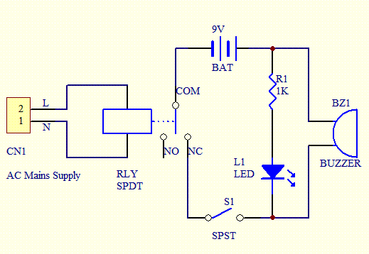
When the mains power supply is available, the relay will be energised and the COM contact will be connected to the NO terminal thus disconnecting the 9V power supply in the circuit. When the mains supply cuts off, the COM will be connected to NC terminal and buzzer will sound. LED will light up. Switch S1 is used to enable or disable the buzzer and LED in the circuit.
Parts List


0 comments:
Post a Comment