
Description.
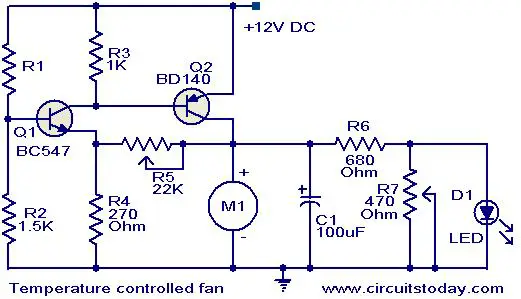
Here is a simple circuit based on two transistors that can be used to control the speed of a 12 V DC fan depending on the temperature.A thermistor (R1) is used to sense the temperature. When the temperature increases the base current of Q1 (BC 547) increases which in turn decreases the collector voltage of the same transistor. Since the collector of Q1 is coupled to the base of Q2 (BD 140), the decrease in collector voltage of Q1 forward biases the Q2 more and so do the speed of the motor. Also, the brightness of the LED will be proportional to the speed of the motor.
Circuit diagram with Parts list.
Notes.
- The R1 can be a 15K @ 20°C ,N.T.C thermistor.
- The M1 can be a 12V,700mA fan motor.
- The capacitor C1 must be rated 25V.
- The circuit can be powered from a 12V PP3 battery or 12V DC power supply.
- Assemble the circuit on a good quality PCB or common board.


0 comments:
Post a Comment