

LED Light Flasher
This is a simple LED flasher project that uses a CMOS 74C04 Integrated Circuit to alternately ON and OFF two LEDs that are connected in parallel. The Hex inverter MM74C04 from Fairchild Semiconductor has a wide operating power supply voltage range from 3V to 15V DC. It has a typical low power consumption of 10nW/package and has high noise immunity. It is back to back compatible with the standard 74 logic family which is freely available in the market. All its inputs have diode clamps to VCC and GND which protect them from damage due to electrostatic discharge.
Schematic Description
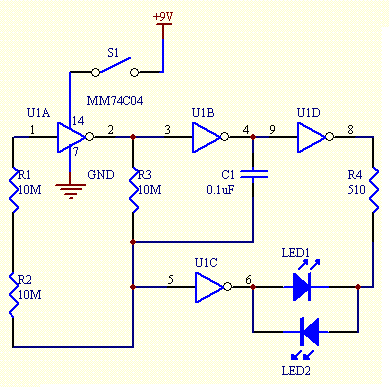
The schematic above shows the simple configuration of the project. It uses two inverters U1A and U1B to form an oscillator configuration where the frequency of the oscillation is given by :
f = 1/[1.4RC]
= 1/[1.4(10 M Ohm)(0.1uF)]
= 0.7 Hz
The square wave frequency of 0.7 Hz is used to feed the input of U1D which is used as a buffer circuit. At the same time, the other inverter U1C gets its input from pins 2 and 3 of U1. With this configuration, when U1D output is high, U1C output will be low and vice versa. In this way when LED1 is ON, LED2 will be OFF and this will alternate at a frequency of 0.7Hz.
The current that goes through the LED is given by:
I = (9V-7V)/510 ohm
= 14mA
It is assumed that the voltage drop across each diode is 2V when it turns ON. One can experiment with the oscillation frequency by changing the values of R1, R2, R3, and C1. The brightness of the LEDs can also be changed by changing the values of the resistor R4. However, always ensure that the current through the LEDs is not exceeded or else the LEDs will be damaged.
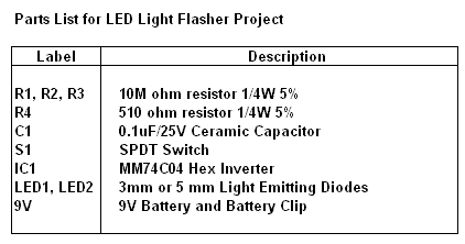
LED Light Flasher Parts List


0 comments:
Post a Comment