
Concept [Toc] [Top]
The current concept incorporates a wireless transmitter and receiver and is thought to be used for remote controlled airplanes or appliances with two seperate parts. In other words, we have one dedicated transmitter (acquisition, filtering) and one dedicated receiver part (user-interface, look-up table, calibration, storage), capable of being connected together with any physical layer, e.g. wired, wireless, infrared. If you want to build a standalone altimeter/variometer just for hiking or mountaineering, this setup can obviously be simplified by omitting the wireless components.
So far, only the transmitter part with all its analog circuitry has been completed entirely - the digital receiver part has still to be done, but does not necessarily have to be a PIC microcontroller. For instance, it could also be a personal computer, connected through the standardized RS232 protocol and a wired/wireless interface to the transmitter part.
The (pending) challenge of the receiver implementation is the field evaluation of the most suitable and accurate temperature and non-linear pressure-altitude correction algorithms. There is maybe need for adding a temperature sensor to the transmitter part.
Receiver [Toc] [Top]
|
Components [Toc] [Top]
The following components have been used: Analog to digital converter NSC ADC12130, a Microchip PIC16F84 controller, a quad op-amp NSC LMC660, a Maxim MAX232 RS232 level shifter, and the Motorola MPXS4100A absolute pressure sensor.
|
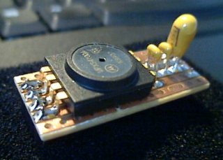
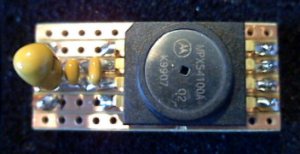
Removable module containing Motorola absolute pressure sensor MPXS 4100A, 10nF and 100nF ceramic and 10uF tantalum capacitors. |
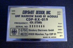
Circuit Design CDP-RX-01 wireless receiver, 434 MHz, up to 7.5 kb/s, uni-directional | |
|
Top view of removable pressure sensor module. |
Circuit design CDP-TX-01 wireless transmitter, 434 MHz, up to 7.5 kb/s, uni-directional |
Technical Data of Wireless Transmitter and Receiver [Toc] [Top]
- Manufacturer: Circuit Design Inc.
- Very small and compact integrated device with robust metal housing.
- Low current consumption, ideal for mobile, battery-powered applications.
- Filter technique using Super-SAW filters.
Additional information is available at Circuit Design Inc. -> Products
Data sheets of wireless transmitter and receiver:
- previous version CDP-TX01 (PDF) discontinued
- current version CDP-TX02 (PDF)
| General | ||
| Oscillator type: | Crystal | |
| Frequency: | 433.920 MHz, 434.075 MHz (Europe) 458.650 MHz (United Kingdom) | |
| Frequency stability: | +/- 2.5 kHz (-10° up to +55° C) | |
| HF channels: | single (fixed channel) | |
| Range: | up to 1000 m (free distance, line of sight) | |
| Baud rate (specified): | 300 - 4800 baud | |
| Bit rate (measured at short distance): | up to 7500 bits/s | |
| Operating conditions: | -10° up to +60° C | |
| Type approval: | I-ETS 300 220 / Germany, France, Switzerland, Sweden, UK, Holland, Austria, EMC |
| Transmitter | ||
| HF power output: | 10 mW +/- 3 dB @ 50 Ohm | |
| Modulation: | FM narrow band | |
| Start-up time: | 30 ms | |
| Input signal type: | digital, 5 Volt | |
| Deviation: | 2.5 kHz | |
| Supply voltage: | 5.5 - 10 Volt | |
| Power consumption: | 18 mA typ. | |
| Dimensions: | 36 x 26 x 10 mm | |
| Weight: | 9.8 g |
| Receiver | ||
| Type: | double superheterodyne, crystal oscillator | |
| Sensitivity: | -120 dBm (12 dB/SINAD, CCITT filter) | |
| Selectivity: | +/- 5 kHz @ -6 dB | |
| Demodulation: | FM narrow band | |
| Distortion: | <> | |
| Output signal type: | digital, open collector | |
| Other outputs: | RSSI and AF | |
| Supply voltage: | 4.5 - 14 Volt | |
| Power consumption: | 10 mA typ. | |
| Dimensions: | 50 x 30 x 7.5 mm | |
| Weight: | 19 g |
Remarks [Toc] [Top]
A lot of people have asked me where I got the Motorola absolute pressure sensor from.
Please see the section Sensor Ordering Information below.
By the way, Motorola distinguishes the sensor characteristics, feature set and package type by the sensor name, so you can also get 4100 sensor types similar to mine with different naming, e.g. MPXT 4100A or PPXA 4100A:
- M Qualified standards
- PX Pressure sensor
- S Small outline package
See Motorola Sensor Selector Guide at the section Documents below.
Evaluation Board [Toc] [Top]
The Circuit Design wireless transmitter and receiver are not necessary to use the evaluation board, since there exists a direct RS232 link to the PC.
Initial Test Setup [Toc] [Top]
|
Test setup to check the initial concept |
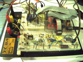
An initial test setup for checking the mixed signal design: A significant problem was the digital noise in the analog circuitry supply voltages. Finally the noise could be minimized by splitting up the power supplies to three independent sources: one digital power supply voltage, one for the sensor and A/D converter, and one supply with slightly higher voltage for the operational amplifiers of the filter stages. The above test setup contains no wireless transmitter, the data is directly transmitted to the computer using the RS232 protocol and a MAX232 level shifter.
In this setup, I have used the LMC660 / LMC662 low-power rail-to-rail quad operational amplifiers for the fourth order Chebyshev filter stages.
PCB Evaluation Board [Toc] [Top]
Moving from the test board to the first PCB, I have only made slight adaptations in the analog part of my design: I have altered the filter characteristics from Chebyshev to Butterworth - but as a consequence, I had to replace the LMC660 operational amplifier by a LM324 type, due to oscillating filters. Conclusion: In the analog world, nothing runs properly if it has not been tested.
If someone knows a good single supply, low-power, rail-to-rail operational amplifier with clean and linear output characteristics in the entire input range, please let me know! The LMC660 is exactly specified this way, but showed up a really bad non-linear characteristic in the upper input range. Bob Krech suggested the LMC6064 precision quad OP amplifier with pin-for-pin replacement for the LM324.
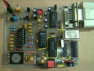 |  | |
| PCB-based evaluation board suitable for first field measurements | ||
|
Description of the above PCB layout |
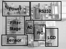
The PCB-based evaluation board consists of analog circuitry at the left side and digital components at the right side of the board. In the upper left corner are the three independent power supplies (5 V analog, 6.8 V analog, 5 V digital), all served from one battery (8 - 10 V). The evaluation board contains further the active Butterworth filter stages built of one LM324 (left side), the NSC ADC12130 A/D converter (center), the PIC 16F84 microcontroller (at right from A/D converter), a dot LCD display and a PORTB connector (lower right corner), a direct RS232 interface with MAX232 level shifter (upper right corner), and an interface for the wireless transmitter allowing for first field measurements (bottom center). The system owns two oscillators. A 4 MHz crystal oscillator provides the conversion clock for the A/D converter, and a separate 4 MHz crystal for the microcontroller allows to increase processor performance easily if necessary. This setup provides two A/D converter input channels: Channel 0 is already used for the pressure sensor, but channel 1 can be used freely, e.g. for voltage surveillance of the R/C receiver battery. If two channels are not sufficient, this system can easily be upgraded to eight channels by integrating the NSC ADC12138 A/D converter. The LCD connector and the RS232 interface serve only for evaluation and debugging purposes in this setup. Finally, the noise characteristics of my approach are very promising!
Although this board is now ready, a suitable R/C plane - my Piper Cherokee - has to be finished first for 'air evaluation'...
![]()
Available Microchip PIC Assembler Code [Toc] [Top]
| Main File | HEX Files |
| View assembler source code: alti_tx.html Download assembler source code: alti_tx.asm (16.7 kB) | alti_tx.hex |
| The above program needs additional include files (modules) to get successfully assembled: m_bank.asm, m_wait.asm, m_rs096.asm | |
| For those, who are not familiar with interfacing a PIC to the RS232 using a MAX232: RS232-Interface.pdf (9.7 kB) | |
Software [Toc] [Top]
An Excel worksheet has been used to visualize the captured data.
With the NSC ADC12130 A/D converter, there are two channels available.
Download Excel worksheet and drivers: alti_2channel.zip (203 kB)
Measurements [Toc] [Top]
I've done some measurements to see whether LSB toggling is sufficient low using the Excel RS232 data capture interface. All measurements have been carried out at room temperature (without any temperature compensation) and without moving the test board. The test period has been one hour with adequate warm-up time for the sensitive analog circuitry (pressure sensor, A/D converter and op-amp).
Note: Because the entire design is laid out very sensitive in order to get a high resolution (in the range of one meter), the accumulated drift could also originate from natural barometric variations.
|
Test setup: Drift of 2 bits during one hour (with a single spike). |
|
Test setup: Drift of 4 bits during one hour. |
|
Test setup: Drift of 3 bits during half an hour. The strange curve comes possibly from temperature variations. |
|
PCB-based evaluation board: The yellow curve represents the pressure sensor, the blue curve is only a test voltage for comparision purposes. The pressure sensor behaves quite stable in conjunction with the PCB setup, only ½ LSB toggling during one hour. The comparision voltage - originating from a simple voltage divider - is even more toggling. This toggling may result from a voltage just reaching the A/D converter LSB threshold. |


Cooking one-pot meals is the way to go when it comes to cold weather camping,
ReplyDeleteso be sure to pack a cast iron dutch oven before you head out
for your camping adventure. As one might have guessed, Si's little nap turns into an overnight stay at Phil and Kay's.
A head light is one of the most essential camping gadgets during
night for the convenience, if there is no power supply at the site of camping.
Feel free to visit my webpage :: Camping And