AddThis

Bookmark and Share

Saturday 25 March 2017

Automated Solar Grass Cutter

The fully automated solar grass cutter is a fully automated grass cutting robotic vehicle powered by solar energy that also avoids obstacles and is capable of fully automated grass cutting without the need of any human interaction. The system uses 6V batteries to power the vehicle movement motors as well as the grass cutter motor. We also use a solar panel to charge the battery so that there is no need of charging it externally. The grass cutter and vehicle motors are interfaced to an 8051 family microcontroller that controls the working of all the motors. It is also interfaced to an ultrasonic sensor for object detection. The microcontroller moves the vehicle motors in forward direction in case no obstacle is detected. On obstacle detection the ultrasonic sensor monitors it and the microcontroller thus stops the grass cuter motor to avoid any damage to the object/human/animal whatever it is. Microcontroller then turns the robotic as long as it gets clear of the object and then moves the grass cutter in forward direction again.
Hardware Specifications
    • 8051 Family Microcontroller
    • Vehicle Body
    • Grass Cutting Blade
    • Solar Panel
    • Motor Driver IC
    • DC Motors
    • Ultrasonic Sensor
    • Robotic Body
    • Capacitors
    • Resistors
    • Voltage Regulator
    • Crystal
    • Led’s
Software Specifications
  • Keil µVision IDE
  • MC Programming Language: Embedded C


Block Diagram

Automatic Irrigation System on Sensing Soil Moisture Content │Smart Irrigation System


In the field of agriculture, use of proper method of irrigation is important. The advantage of using this method is to reduce human intervention and still ensure proper irrigation.

The project uses an 8051 series microcontroller which is programmed to receive the input signal of varying moisture condition of the soil through the sensing arrangement. This is achieved by using an op-amp as comparator which acts as interface between the sensing arrangement and the microcontroller.

Once the controller receives this signal, it generates an output that drives a relay for operating the water pump. An LCD display is also interfaced to the microcontroller to display status of the soil and water pump. The sensing arrangement is made by using two stiff metallic rods inserted into the field at a distance. Connections from the metallic rods are interfaced to the control unit.

The concept in future can be enhanced by integrating GSM technology, such that whenever the water pump switches ON/OFF, an SMS is delivered to the concerned person regarding the status of the pump. We can also control the pump through SMS.

Robotic CPR Machine

 Continuing with our "robots saving lives" theme, check out the robotic CPR machine that a Staffordshire, UK ambulance service has put in 100 of its ambulances. The Daily Mail says, "In only 20 seconds, the machine can be ready to perform compressions on a sick patient, which maximises their chances of survival." The machine can keep up chest compressions for as long as necessary by using compressed air and pumps.


Railway Track Fault Detection

Here we propose an innovative approach to detect railway track crack as this system detects crack based on image processing. Many image preprocessing steps is used to detect railway track crack. As image is prone to noise. System converts image to grayscale image and uses filtering to remove noise from image. Noise removal helps to detect crack more accurately. Image luminous level is increased and image is converted to binary image. This helps system to detect only crack and helps to remove other unwanted objects. Image once converted to binary image, holes are filled by using image processing method this helps to reject all smaller objects which are not required for crack detection. Intensity value is used for accuracy purpose. Blob analysis method is used to detect large blobs. System detects crack based on number of connected components. System detects crack based on number of blobs involved and mentions whether crack exist or not. Using bounding box functionality, system displays rectangular box around the blob. This system used during railway track inspection. The proposed system is able to detect deeper cracks with 80% success rate and minor cracks with 50-60% accuracy                                                                                                            

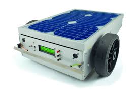
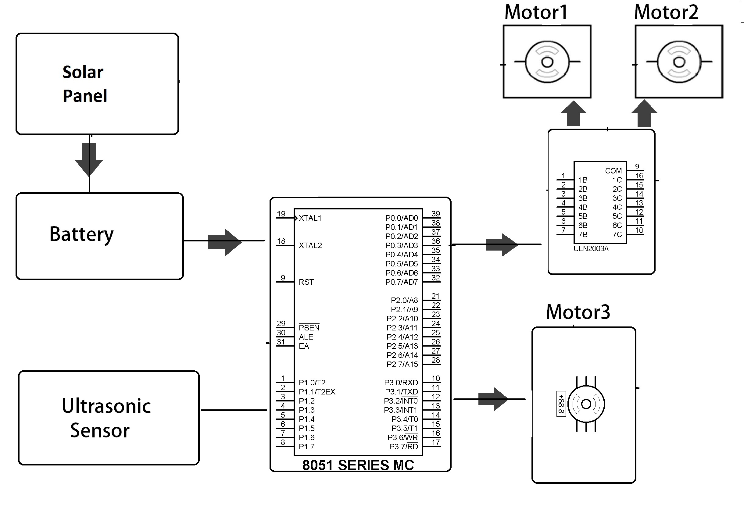
     Ultrasonic detection is the method used. When the vehicle detects a crack, it sends a signal to the control room. While it is on the track, the device does not hinder movement of trains. When a train arrives, the device, which uses a pneumatic system, shrinks. The detector helps view the cracks on the track and its GPS system allows locating the vehicle.                                                                                               
1. Automatic Broken Track Detection Using LED-LDR Assembly

2. Robust Railway Crack Detection Scheme Using Led-Ldr

3. Robust Railway Crack Detection Scheme (RRCDS) Using LED-LDR

4. Automatic Broken Rail Crack Detection Scheme

5. Download – International Journal of Advanced Technology

6. Railway track crack detection robot project

7. Railway track crack identification

8. Crack Detector Robot Using LED-LDR

9. Searches related to led-ldr based railway crack detection scheme

10. robust railway crack detection scheme using led-ldr assembly report

11. robust railway crack detection scheme (rrcds) using led-ldr assembly

12. robust railway crack detection scheme using led ldr assembly ppt

13. railway track crack detection system using microcontroller

14. automatic railway track crack detecting vehicle project pdf

15. railway track crack detection system project report

16. railway crack detection circuit diagram

17. railway crack detection robot

18. railway track crack detection system project ppt

19. railway track crack detection project report

20. automatic railway track crack detecting vehicle ppt

21. robust railway crack detection scheme ppt

22. railway track crack detection system project report

23. railway track crack detection system ppt

24. railway crack detection using led ldr ppt

25. Automatic Railway Track Crack Detection

26. IOT: Railway track crack detection robot USING GSM-GPS

27. IOT: Crack detection Robot For Railway track Inspection

28. Railway track crack detection and SMS alerting System

29. Railway tracks crack detection

30. Crack detection Robot For Railway track Inspection

31. Microcontroller based Railway Crack Detection

32. Solar powered railway track crack detection using GSM GPS

33. Railway track crack detection and SMS alerting System

34. Railway track crack detection robot project

35. railway track crack detection autonomous vehicle

36. Robust Railway Crack Detection Scheme Using Led-Ldr

37. CRACK DETECTION SYSTEM FOR RAILWAY TRACK

38. Railway track, crack detection, ARM, GSM, GPS

39. Automatic detection of squats in railway track

40. IOT: Railway track crack detection robot USING GSM-GPS

41. Robust Railway Track Crack Detection Scheme

42. Railway track crack detection robot project

43. A Modern Method for Detecting Cracks In Railway Tracks

44. automated visual inspection of detecting cracks and obstacles on rail

45. 30+ Awesome Internet of Things Project Ideas | mbed

46. crack detection and collision avoidance in railway using arm

47. Automatic Broken Track Detection Using IR Transmitter

48. automatic identification of obstacles and crack sensing scheme in rail

49. AUTOMATIC RAILWAY TRACK FAULT IDENTIFIER

50. Innovative Railway Track Surveying with Sensors

51. 40+ GSM Based Projects for Engineering Students – Electronics

52. A Wireless Approach with Sensor Network for Real Time

53. Solar powered railway track crack detection using GSM GPS

54. A New Novel Control Algorithm/Scheme To Detect Cracks/Damages

55. intelligent railway crack inspection robot

56. Robust Railway Crack Detection Scheme Using ARM IRTRDS Algorithm

57. a microcontroller based stout robot with automatic crack detection

58. Railway Track Security by GSM With User Programmable

59. innovative railway track surveying with sensors and controlled

60. Robot section:GPSMEMS SensorUltrasonicsensorGSM Train

61. MEMS sensor is used for detect the cracks and breakage of tracks.

62. A Novel Approach Railway Track Damage Detection Robot

63. Gps based railway crack detection

64. A microcontroller based stout robot with automatic crack
detection in railway tracks using led ldr

65. Railway Level Crossing Gate Control & Measurement

66. ROBOT WITH AUTOMATIC CRACK DETECTION IN RAILWAY TRACKS

67. ppt on railway track crack detection robot using gsm gps

68. Latest GSM Based Projects for final year engineering students

69. Get new IOT Projects Ideas & Training, IEEE Internet Of Things (IoT)

70. MONITORING OF CRACK INSPECTION AND MAPPING IN RAILWAY

71. Railway Track Monitoring System using GSM Module

72. SMART ROBOT FOR RAIL TRACK FLAW DETECTION USING NDT

73. Railway Security System based on Wireless Sensor Networks

74. An Intelligent Design to Detect Broken Track for Indian Railway

75. Railway Track Crack Detection And Sms Alerting System

76. Innovative Railway Track Surveying with Sensors

77. Railway Track Crack Detection Videos

78. Crack Found On Rail Track

79. Review of Railway Track Fault Finding System

80. Broken Railway Track Detection Using LED-LDR

81. Railway track, crack detection, ARM, GSM, GPS, Auto matic Rail crack detection, GPRS.

82. Low Cost Rail Crack Inspection System

83. Railway Track Fault Detection Project

84. rail robot: autonomous robot can clean and monitor your railway tracks

Monday 20 March 2017

Energy Meter Reading Over Internet

e conventional energy meter reading system may cause low accuracy and low efficiency. This project, energy meter reading over internet facilitates the display of units consumed and cost over the internet (in the form of chart and gauge).


The project block diagram is shown in the above figure which consists of various blocks such as microcontroller, energy meter, LDR, load, LCD display, GSM modem, and power supply block. The digital energy meter used in this project consists of blinking LED (for 1unit it flashes 3200 times) which is interfaced with 8051 microcontroller through LDR. Thus, the LDR generates an interrupt for every LED blink and is fed to microcontroller. The microcontroller takes the reading and displays the same over LCD interfaced with microcontroller.

IOT Based Home Automation

IOT or internet of things is an upcoming technology that allows us to control hardware devices through the internet. Here we propose to use IOT in order to control home appliances, thus automating modern homes through the internet. This system uses three loads to demonstrate as house lighting and a fan. Our user friendly interface allows a user to easily control these home appliances through the internet. For this system we use an AVR family microcontroller. This microcontroller is interfaced with a wifi modem to get user commands over the internet. Also we have an LCD display to display system status. Relays are used to switch loads. The entire system is powered by a 12 V transformer. After receiving user commands over the internet, microcontroller processes these instructions to operate these loads accordingly and display the system status on an LCD display. Thus this system allows for efficient home automation over the internet.
The purpose of this project is to remote monitoring and control of the Digital Energy Meter. This system enables the Electricity Department to read the meter readings regularly without the person visiting inside each house. This can be achieved by the use of Microcontroller unit that continuously monitors and records the Energy Meter readings in its permanent (non-volatile) memory location. This system also makes use of a RF
Transceiver for transmitting the readings of Energy Meter. RF Communication ranges in between 30 KHz to 300 GHz. RF communication works by creating electromagnetic waves at a source and being able to pick up those electromagnetic waves at a particular destination. These electromagnetic waves travel through the air at near the speed of light. The wavelength of an electromagnetic signal is inversely proportional to the frequency; the higher the frequency, the shorter the wavelength. RF transceiver has both transmitter and receiver section with it. The Microcontroller based system continuously records the readings and the live meter reading can be sent to the Hand held device. The receiver end comprises of RF Transceiver, which receives the data from the transmitter. The data received at the receiver end is fed to the microcontroller present at the receiving end. The microcontroller at the receiving end is provided with a LCD. The readings received is processed and displayed on the LCD. The Microcontroller is programmed using Embedded C language.