
1. Double image mixing for D stereoscopic vision
2. Common Challenges in Image Processings
3. Radar guidance systems
4. Radio broadcasting system : Design and Application
5. Video Streaming Technology in G Mobile Communication Systems
6. Edubuntu: Linux for Young Human Beings
7. Wireless Video Service in CDMA Systems
8. Challenges to Nextgeneration Internet Internet
9. Network Virus
10. Recent Advances in Speech Recognition and Speaker Verification HDMI and DisplayPort: How it works
11. Flat screen display systems
12. Performance Evaluation Of Hybrid OFDM/CDMA/SFH Approach For Wireless
13. Software based GPS receiver
14. MPEG and H. Scalable Video Coding
15. Security Analysis of Authentication Watermarking System
16. The impact of Cognitive Radio for Exploiting Underused Spectrum
17. Investigation of the types of handovers in wireless communication system
18. Challenges to Next-generation Internet Internet III
19. SpaceTime Coding For FrequencySelective Fading Channels
20. The Winner II Channel Model
21. Radio Frequency Identification: Reader Circuit & Antenna Circuit Design
22. Image Segmentation
23. Biometrics-based pattern recognitions
24. Making D animation movies
25. Analog to Digital Conversion System : Theory and Application
26. WiMax and G LTE : Complement or Competitor
27. ASIC Design Flow
28. Wireless Security Enhancement from the Lowest Layer
29. Performance of Dual Core Processors
30. Advances in Signal Processing and Artificial Intelligence Technologies in the Classification of Power Quality Events
31. The Difference between ANN and HMM
32. Sound separation techniques
33. Face Recognition Technology
34. Deep Space Engineering Application
35. E-commerce Technology Challenges
36. Trans ocean intercontinental optical links
37. WARP : Wireless Open Access Research Platform
38. Common Challenges in Image Processing
39. HCI for Mobile devices
40. Study of Latest Issues Pertaining to Image Transmission in Wireless Network
41. Mobile and Broadcasting Convergence as a Disruptive Force
42. Adaptive modulation Performance of wideband OFDM communications
43. Spectrum Requirement for WINNER Wireless World Innitiatives II
44. Securing Wireless Communications
45. Jamming and AntiJamming Technologies for Law Enforcement
46. Indoor Positioning
47. Securing Wireless Communication
48. The Marriage of Cryptography and Watermarking
49. The study of propagation models in communication system
50. Radio Frequency Identification: Evolution of Reader Circuit Design
51. Telemedicine
52. MIMO in .n: potential and challenges
53. Equalization and interference cancellation for TDMA wireless
54. The future of wireless network infrastructure
55. EMG Signal Analysis: Detection, Processing, Classification and Applications
56. Sensors and Their Application in Robotics
57. WARP: Wireless Open Access Research Platform
58. MAC Layer enhancement in .n standards
59. Visible Light Communications
60. Soliton pulses in long distance communications
61. Biometrics-applications based pattern recognitions
62. Ambient Intelligence: the networking challenges
63. Challenges to Next Generations Internet Internet
64. Future evolution of microprocessor from single core to multi core
65. MPEG and H. : Scalable Video Coding
66. Deep Space Application
67. Introduction to Biomechatronics System
68. Study on the use of D Image Processing in Medical Imaging
69. Space-Time Coding For Frequency-Selective Fading Channels
70. Quality Assessment Technique for Compressed Video
71. Secure Localization Algorithms
72. Enabling Adaptive Transmission Using Fading Prediction
73. Radio Frequency Identification: Evolution of Transponder Circuit Design
74. Recent advances in speech recognition and speaker verification
75. Jamming and Anti-Jamming Technologies for Law Enforcement
76. Analog To Digital Conversion
77. Introduction to Grid Computing
78. Design of cryptographic protocols
79. The impact of Cognitive Radio for Exploiting Under-used Spectrum
80. A Comparison Study between Bees Algorithm and Ant Algorithm
81. Wireless communication : Past, present and future
82. Radar Tracking System : Concept and Application
83. Equalization and interference cancellation for TDMA wireless Communication systems
84. Radar Guidance System
85. Takeover: A New Vertical Handover Concept
86. Security in the digital documents
87. Comparision of Edge Detection Algorithms
88. Biometrics Application Based Pattern Recognitions
89. Environmental Observation and Forecasting Systems using Wireless Sensor Networks.
90. The Winner Wireless World Innitiatives II Air Interface
91. Earthquake Detection Using FM Radio
92. High performance computing using graphic card and multicore processor
93. Security Analysis of Authentication Watermarking Systems
94. Video compression Techniques
95. FoIP vs VoIP : Design and Application
96. Trans ocean inter-continental optical links
97. Image Compression, Past and Present
98. A comparative study of web cost estimation model for hypermedia applications
99. Radio Frequency Identification: Evolution of Antenna Circuit Design
100. Network Virus : Creation and Prevention
101. WiMax and G LTE : complement or competitor?
102. Transocean Inter Continental Optical Links
103. Security Architectures
104. IPTV vs Mobile TV : Design and Application
105. HDMI and Display Port : How It Works
106. Smart Home Technologies
107. Emerging Communications Technologies and their impact on Military Communication Systems
108. Engineering and Quran
109. Security of the digital documents
110. Performance Evaluation Of Hybrid OFDM/CDMA/SFH Approach For Wireless Multimedia
111. Image Compression System for Mobile Communication : Advancement in the Recent Years
112. Streaming technology in G mobile communication systems
113. Comparison between Vertical Handover Decision Algorithms for Heterogeneous Wireless Networks
114. Study of Image Enhancement in Spatial Domain vs Frequency Domain
115. Video Image Compression Techniques
116. Security in WiMAX Networks
117. Comparison Study between Bees Algorithm and Ant Algorithm
118. Comparative Analysis of the Physical Layer Technologies in WiMax and LTE
119. Radar Tracking System: Concept and Application
120. E-Commerce Technology Challenges
121. Wi-Max
122. Single Phase Trams Nehal Shahformer Construction & Design
123. Cable Modem
124. Common Channel Signalling System 7
125. I-Mode
126. Gigabit Ethernet
127. Speed Control Of DC Motor Using Fuzzy Logic
128. Multi Detection & Tracking
129. Distributed Control System
130. Hydrogen Fuel Cell
131. LIDAR
132. Continuous Speech Processing (CSP)
133. Complete Weighing Solution Using Momentum PLC
134. Process Control Through GSM Communication
135. Telerobotics Operations Via Internet
136. Development Cycle For Microcontroller Based Systems
137. Access Network Fiber To The Building(AN-FTTB)
138. Future Telephony Networks
139. Speech To Text Conversion
140. Practical Advances In Asynchronous Design
141. Space Vector PWM
142. Wafer Bumping
143. Impedence Glottography
144. Wireless Sensor N/W Tech And Its Applications Using VLSI
145. Application Of CNC(Computer Numeric Control)
146. Dolby Sound Processing
147. Erbium Doped Fiber Amplifier
148. Choices For CNC
149. DSL Technology
150. Covolutional Encoding & Viterbi Decoding
151. Industrial Automation Using I2C Protocol.
152. Control & Cancellation Of ECHO In Telephony
153. Control & Cancellation Of ECHO In Telephony
154. Evdo (Evolation Data Only)
155. IP Spoofing: A Network Threat
156. In Band On Channel Digital Audio Broadcasting
157. Zigbee
158. Optical DWDM Networks
159. Space Division Multiple Access (SDMA)
160. Blue Ray DVD
161. Multicasting
162. Automative Electronics
163. Expert Systems
164. Magnetic RAM
165. Speed Control Of 3 Phase Induction Motor Using V/F
166. On Chip Designing Factors & Their Solution
167. Image Transform & Compression Using Wavelet.
168. SNMP Simple Network Management Protocol
169. Walking Beam Control Using PLC
170. PID Controller
171. Enhancing Perfprmance Using An ARM Microcontroller With Zero Wait State Flash
172. Peripheral Interface Controller
173. Cordect Tech
174. Convergence & Multimedia Networking
175. CANOPEN
176. FPGA Devlopement And Challenges
177. Effect Of B.W On Speech Intelligibility
178. Huperspectral Inaging
179. Embedded FPGA
180. Harmonic Reduction In AC Drives.
181. Multi Protocol Label Switching In Optical Networks
182. Modbus Protocol
183. Multi Service Network Based On ATM
184. Revolution Of Transistors(Tri Gate Transistors)
185. Biosensors
186. Motes
187. Cybernetic Organism
188. Imax Technology
189. Spam
190. Brain Computer Interfacing
191. Cellular Communication -4G
192. Orthogonal Frequency Division Multiplexing (OFDM)
193. DEMO
194. CO2 Laser
195. T-Rays
196. Fuel Cell Vehicle
197. Plasma Antenna
198. Wi-Fi
199. Photocopier Technology
200. Seismology and its Instruments
201. Nems-(Nano-electro-Mechanical System)
202. Quantum Cryptography
203. Free Space Optics
204. Data Storage Technologies
205. Grid Computing
206. RTOS(Real time Operating System)
207. Tele Presence Surgery
208. Quantum Comuting , Telepotation & Telemmersion
209. Digital Watermarking
210. Optical Coherence Tomography
211. USB Pen Drive Disk
212. Sensor Network
213. Optical Packet Switching
214. Safe in Flight Mobile Telephony
215. MODBUS
216. Embedded Webserver
217. Hyper-Threading
218. Internet Over Power Line
219. Multiprotocol Label Switching
220. Morphological image processing
221. Embedded Networking
222. Optical Burst Switching
223. Protected Extensible Authentication Protocols
224. Positron emission tomography
225. Face Recogtion
226. Interplanetary Internet
227. Field Emission Display
228. System on Chip
229. Micro Opto Electro Mechanical System
230. Digital finger Printing
231. Virtual Instrumentation
232. Cellular Mobility
233. Image Enhancement
234. MODBUS
235. Ibutton
236. Wireless Instant Messaging (WIM)
237. Metor Burst Communications
238. GaAs Technology and its Applications
239. Virtual Private Network (VPN)
240. Mobile IP
241. Digital Steganography
242. Ultra wideband
243. Aerospace telemetry
244. Color Image Processing
245. Digital enhanced Cordless telecommunications
246. Viruse on Mobile
247. Optical Computing : The wave of Future
248. Colour Doppler
249. Image Compression
250. Seiral ATA
251. Signaling System 7 (SS 7)
252. PHY layer of FBWA
253. VDSL
254. E “ Faxing
255. Steganography
256. GPRS
257. Dual Polarized Antenna
258. High Speed Serial Interface
259. Touch screen Technology
260. Interactive Informative Mobile Service
261. Biometrics
262. Digital Display using DLP
263. CPLD
264. Snake Robot
265. E “ Clothing
266. UWB Technology
267. Optical Time Division Multiplexing and De multiplexing Techniques
268. Adaptive Antenna Technology for Mobile Communication
269. Tele “ Immersion
270. Bone growth using electrical stimulation
271. Intel Itanium Processor
272. DAMA
273. Aircraft Security
274. WPAN
275. Sonar
276. System In Package (SiP)
277. Cryptography
278. Projection TV
279. Digital Photography
280. Image Processing and its application
281. Digital Audio Broadcast (DAB)
282. Ad-Hoc Network
283. D “ Amps
284. Low Voltage Differential
Popular Posts
-
Introduction This amplifier does not claim to be "state of the art", and in fact the base design is now over 20 years old. It is ...
-
RESEQUENCING ANALYSIS OF STOP-AND-WAIT ARQ FOR PARALLEL MULTICHANNEL COMMUNICATIONS:--DOTNET--2009 RESEQUENCING ANALYSIS OF STOP-AND-WAIT AR...
-
Signals, including those used for communication between occupants of a car or train.Indicators, recorders, telegraphic, telephonic, or oth...
Thursday, 17 May 2012
DEAD-TIME ELIMINATION FOR VOLTAGE SOURCE INVERTERS
A novel dead-time elimination method is presented in this paper for voltage source inverters. This method is based on decomposing of a generic phase-leg into two basic switching cells, which are configured with a controllable switch in series with an uncontrollable diode. Therefore, dead-time is not needed. In comparison to using expensive current sensors, this method precisely determines the load current direction by detecting which anti-parallel diode conducts in a phase-leg. A low-cost diode-conduction detector is developed to measure the operating state of the anti-parallel diode. In comparison with complicated compensators, this method features simple logic and flexible implementation. This method significantly reduces the output distortion and regains the output RMS value. The principle of the proposed dead-time elimination method is described in detail. Simulation and experimental results are given to demonstrate the validity and features of this new method.
- Introduction
To avoid shoot-though in voltage source inverters (VSI), dead-time, a small interval during which both the upper and lower switches in a phase-leg are off, is introduced into the standard pulse width modulation (PWM) control of VSIs. However, such a blanking time can cause problems such as output waveform distortion and fundamental voltage loss in VSIs, especially when the output voltage is low.
To overcome dead-time effects, most solutions focus on dead-time compensation by introducing complicated PWM compensators and expensive current detection hardware. In practice, the dead-time varies with the gate drive path propagation delay, device characteristics and output current, as well as temperature, which makes the compensation less effective, especially at low output current, low frequency, and zero current crossing. Several switching strategies for PWM power converters have been proposed to minimize the dead-time effect. A dead-time minimization algorithm was also discussed earlier to improve the inverter output performance. A phase-leg configuration topology proposed prevented shoot through. However, an additional diode in series in the phase-leg increases complexity and causes more loss in the inverter. Also, this phase-leg configuration is not suitable for high-power inverters because the upper device gate turn-off voltage is reversely clamped by a diode turn on voltage. Such a low voltage, usually less than 2 V, is not enough to ensure that a device is in its off-state during the activation of its complement device.
Friday, 11 May 2012
Protection of Low-Voltage DC Micro-grids
LV dc microgrid is used to interconnect distributed
resources and sensitive electronic loads. To ensure reliable operation of the
LV dc microgrid, it is important to have a well-functioning protection system.
When designing an LV dc microgrid protection system, knowledge from existing dc
power systems can be used. However, in most cases, these systems use
grid-connected rectifiers with current-limiting capability during dc faults. In
contrast, an LV dc microgrid must be connected to an ac grid through converters
with bidirectional power flow and, therefore, a different protection-system
design is needed. In this paper, the operating principles and technical data of
LV dc protection are presented. Furthermore, different fault-detection and
grounding methods are discussed. The influence of the selected protection
devices and grounding method on an LV dc microgrid is studied through
simulations. The results show that it is possible to use available devices to
protect such a system.
Sunday, 6 May 2012
Gas Leak Detection
Abstract
The aim of the project is to develop a gas leak detection and location system for the production safety in Petrochemical Industry.
PURPOSE:
The purpose of the project is to monitor gas leakage parameter. When they exceeds threshold, intimation is given to the nearby control section including readings of parameter and location of the gas leakage.
Description:
The system is based on Wireless Sensor Networks (WSN) it can collect the data of monitoring sites wirelessly and sent to the computer to update values and the location also. Consequently, it can give a real time detective of the potential risk area, collect the data of a leak accident and locate the leakage point. However the former systems cannot react in time even cannot obtain data from an accident and locate accurately.
The paper has three parts, first, gives the overall system design, and then provides the approaches on both hardware and software to achieve it. The gas leak detection and location system consists of three parts: control center and terminal nodes.
Here the supervising control center is based on arm controller, it displays the location and the status messages of parameters of all the monitoring sites, and it is a graphical description of the geographical information of the entire potential risk area. Status, sensor data and location data, and then sent them to the control center to update value in the location software
TECHNOLOGY:
Zigbee is new wireless technology guided by IEEE 802.15.4 Personal Area Network standard. It is primarily designed for the wide range controlling applications and to replace the existing non-standard technologies. It currently operates in 868 MHz band at a data rate of 20Kbps in Europe, 914MHz band at 40kbps in USA, and the 2.4GHz ISM bands Worldwide at a maximum data-rate of 250kbps. It is used to verify whether user's truncation is possible or not. One of the main advantages of this ZIGBEE communication is that it provides a noise free communication, the amount of noise added in this type of communication is very less compared to the other wireless communications
RESULT:
Hence a gas leak detection and location system for the production safety in Petrochemical Industry was designedAttendance Management Using Face Recognition System
The aim of this project is to deal with the problem of face detection in color images. Unlike in face recognition, where the classes to be discriminated are different faces in face detection, the two respective classes are the “Face area” and the “Non face area”. The novel approach to face detection is presented, binarisation rules especially designed for a skin area detection within a image frame.
The process involves Binarisation, localization, training and identification of Human Face.
This project easily extract the human face from any other images. Image segmentation algorithm is used to identify the face from other images.
After recognizing the face, the PC puts the attendance for the particular user. Also it sends signal to the microcontroller through serial port. The microcontroller analyses the signal and operates the door motor through driver section. The microcontroller program is written in assembly language. The microcontroller used is PIC 16F73
In this project, the camera is replaced by CD drive. The face is stored in the CD. As soon as the particular CD is inserted, the software in the PC recognizes the face and sends signal to the microcontroller through serial port. The PC recognizes the face and checks the data with the existing data. If it matches with any data, it puts attendance for the particular user. Also it sends signal to the microcontroller
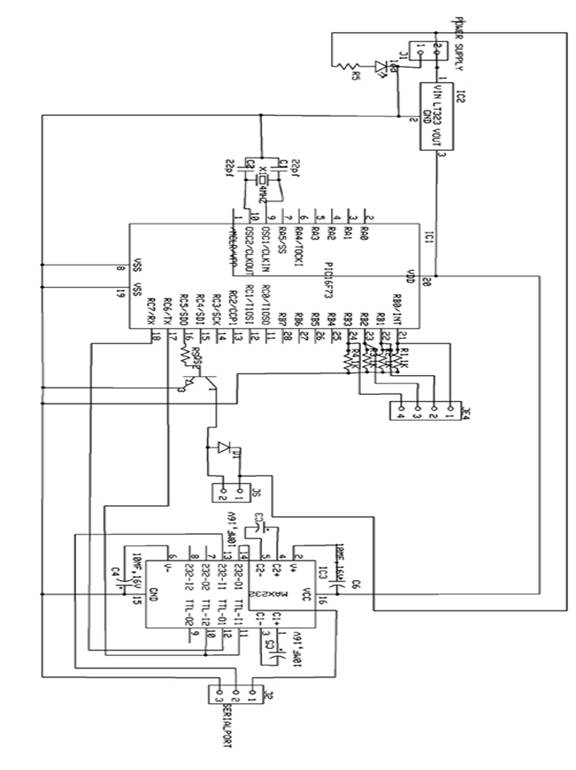
The microcontroller used in this circuit is PIC16F73. It is a 28 pin IC with three I/O ports. It has inbuilt ADC. According to the signal received from the camera, the values are stored in the RAM of the microcontroller. Accordingly the microcontroller controls the door motor through driver section and relay. The microcontroller program is written in assembly language. The assembly language program is compiled to form “hex” code. The “hex” code is written in the microcontroller using PIC write software with the help of PIC writer.
Bluetooth Energy Meter
Abstract
The word automation brings to mind devices that operate with minimal human intervention. In other words, acting or operating in a manner essentially independent of external influence or control. It finds application in controlling industrial equipments, home appliances, computer peripherals and robots. Bluetooth is a promising new wireless technology, which enables portable devices to form short-range wireless ad hoc networks and is based on a frequency hopping physical layer. Bluetooth is a frequency hopping system, which defines multiple channels for communication (each channel defined by a different frequency hopping sequence). A group of devices sharing a common channel is called a piconet. Each piconet has a master unit, which selects a frequency hopping sequence for the piconet and controls the access to the channel. Other participants of the group known as slave units are synchronized to the hopping sequence of the piconet master
Home and office automation using Bluetooth enabled devices have generated sufficient interest in the networking community. Bluetooth based automation offers flexibility, even when the devices actually present far from the master unit. The commands for the automation unit are given through the software module in PC. From PC the command is given to Bluetooth USB adapter. The Bluetooth USB adapter enables the Bluetooth communication and converts the data into airborne signals. The Bluetooth transceiver has a built-in antenna receives the air borne signals and transfer the data to the embedded controller through serial port. The Bluetooth transceivers can be operated in point-to-point, point-to-multipoint and multipoint-to-multipoint architectures.
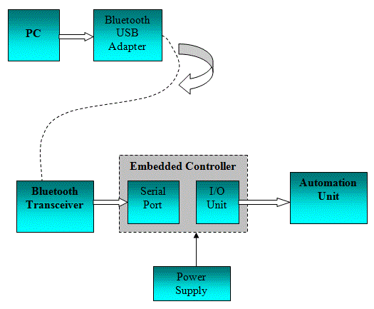
The embedded microcontroller is programmed to read the data. The embedded controller is the CPU that decides the operation of the automation unit. The embedded controller used here is 89C51 microcontroller. It is a derivative of 8051 microcontroller whose architecture and instruction set are same as 8051 microcontroller with some additional functionality. Since the controller has the inbuilt peripherals it is called as embedded controller. The embedded controller controls the automation unit as per the commands. Bluetooth based systems are developed to manage proper safeguards to prevent unauthorized leakage of information. Synchronizing data between cell phones, laptops, and PDAs; using cell phones as cordless phones when at home; and connecting PDAs to the office LAN are some of the cumbersome things that are possible with Bluetooth
Design of a Wireless Medical Monitoring System
Design of a Wireless Medical Monitoring System
Abstract
The main aim of this project is used Monitoring Terminal and it can detect the patient's real-time body temperature, heart rate and other physiological informations, and transmit them to the control center.
PURPOSE :
Now days the fast development and popularization of information processing and wireless data transmission technology, the research of wireless Medical Monitoring System has became a hot topic with the help of biomedical sensors. By utilizing the wireless technique to transmit information between medical sensor and monitoring control center, the free space of patients is enlarged, and the efficiency of the modern management of hospitals is improved
DESCRIPTION:
Now a day with the increase of biomedical sensor we are going into this process of detecting the patient's real-time body temperature, heart rate and other physiological information's .Coming to the main core of wireless medical monitoring system is the design of wireless monitoring terminal, and the development of system software. The monitoring terminal generally consists of three modules: the sensor module, the control module, and the wireless communication module. The sensor module is used for acquiring medical information from the outside, and then converts them to digital signals. The control module is often compared to the brain of monitoring terminal, which is in charge of coordinating the task of different modules, controlling the sensors, processing data, and executing communication protocols.
The wireless communication module mainly deals with the wireless transmission of information. Nowadays, there are various kinds of wireless communication protocols. But since the main task of a monitoring terminal is to realize the transmission of signals such as heart rate, body temperature, and calling signals the data traffic is not heavy. Moreover, because the monitoring terminal is worn on patients, which needs to be supplied by battery, it puts a high demand on the reducing of power dissipation of wireless transmission module. Having taken these comprehensive factors into consideration, this paper chooses the ZigBee technology as the wireless communication protocol. ZigBee technology is a shortrange, low-rate, low-power wireless communication technology
TECHNOLOGY:
Zigbee is new wireless technology guided by IEEE 802.15.4 Personal Area Network standard. It is primarily designed for the wide range controlling applications and to replace the existing non-standard technologies. It currently operates in 868 MHz band at a data rate of 20Kbps in Europe, 914MHz band at 40kbps in USA, and the 2.4GHz ISM bands Worldwide at a maximum data-rate of 250kbps. It is used to verify whether user's truncation is possible or not. One of the main advantages of this ZIGBEE communication is that it provides a noise free communication, the amount of noise added in this type of communication is very less compared to the other wireless communications
Hence, by implementing this project the monitoring terminal can precisely check the heart rate and body temperature of patients, and send them to coordinator and then surveillance center through wireless network.
Solar Based Electromagnetic Braking System
The objective of this project is to design the solar based Electromagnetic breaking system using Object sensor for Automobiles. This project is mainly used in Vehicles either two or four wheelers. In this project is used in real time we can avoid so many accidents.
Brief Methodology:
This project is designed by following blocks
• Microcontroller
• Solar panel with battery.
• Object sensor
• Driver circuit
• Relay
• Electromagnetic core
• Breaking system
The object sensor senses the object and gives corresponding signals. These electrical signals are very small mill voltage signal, so it is given to amplifier circuit. The amplifier circuit is constructed with operational amplifier which acts as power amplifier. Then the amplifier signal is given to signal conditioning unit which also constructed with operational amplifier. In this circuit operational amplifier act as comparator and generate the square pulse given to microcontroller. The microcontroller may be ATMEL/PIC/RENESAS/ARM microcontroller. It will work according to our object already we have programmed.
According to the object sensor value, the microcontroller activates the driver circuit as per mentioned in the program. The driver circuit is constructed with transistor which acts as switch to control the relay. The relay output is directly connected to the electromagnetic core which is attached in the breaking system.
Whenever we control the brake, at the time what happens in the system means one of the coil winding is placed around it. It generates the electromotive force and it's fitted with the suitable mechanical set. Likewise when we release the break the force generation will be stopped and the coil winding releases from the mechanical set.
Entire kit is controlled by only solar power. Solar panel consists of number of silicon cells, when sun light falls on this panel it generate the voltage signals then these voltage signals given to charging circuit. Depends on the panel board size the generated voltage amount is increased. In charging circuit the voltage signal from the board is gathered together and stored in the battery. The battery power is used to control the vehicle
Advantage:
- Can use all type of vehicles
- Low cost
- Low power consumption
Body Motion Information Collection
Abstract
This project is utilizes multiple- Knot network technology to gather multiple –point accelerations information's.
PURPOSE:
This paper deals with the Numerous experiment data indicate it gather accurate information about human body which reflect the truthfully human body motions and this paper is process or transmit it to advanced comprehensively analyzed and this is widely used in such fields are health recovery training, physical exercises, computer games controlling. And here some mathematical calculations about the acceleration component information such as motional track and dynamic process will be gotten for this platform
Description:
Any human body motion, from its beginning to the end, the acceleration of every part of the mobile limbs or other parts of human body is keeping changing. If certain motion is repeated, then its acceleration changing regularity is also very also very close. Therefore if a three-axis acceleration sensor is put on some typical point of measured limbs or other body parts, then the three acceleration components X_Y_Z of that typical point in the motion process can be collected accurately.
Then by mathematical calculation about the acceleration components information such as the motional track and dynamic process about that point will be gotten.
From comprehensive analysis of the data gathered about several typical points detailed information about the measured human body motions is obtained so that motion information is digitalized.
This motion information collection platform uses multi-knot internet technology to
Collect the acceleration information of multiple typical points simultaneously, and process or transmit it to advanced computers to be comprehensively analyzed, thus this platform can be widely used in such fields as health recovery training, physical exercises, computer games controlling
TECHNOLOGY:
Micro-Electro-Mechanical Systems (MEMS) is the integration of mechanical elements, sensors, actuators, and electronics on a common silicon substrate through microfabrication technology. While the electronics are fabricated using integrated circuit (IC) process sequences (e.g., CMOS, Bipolar, or BICMOS processes), the micromechanical components are fabricated using compatible "micromachining" processes that selectively etch away parts of the silicon wafer or add new structural layers to form the mechanical and electromechanical devices.
MEMS promises to revolutionize nearly every product category by bringing together silicon-based microelectronics with micromachining technology, making possible the realization of complete systems-on-a-chip . MEMS is an enabling technology allowing the development of smart products, augmenting the computational ability of microelectronics with the perception and control capabilities of micro sensors and micro actuators and expanding the space of possible designs and applications
RESULT:
By this controller we get the information according to motion of the body.
SMS Controlled Industrial Controller
In a process control industry, it is very difficult for a person to be present or to monitors the system continuously. If not, there occurs damage in the whole process industry. In order to view the process continuously and to check the status of the process we are going to use our project “SMS CONTROLLED INDUSTRIAL CONTROLLER”. This project has been implemented in various platforms, now we are going to do this project using LABVIEW Here we can monitor any number of process parameters. The hardware unit consists of all the hardware requirements needed for the process.
This project is implemented by using LABVIEW software to send the message when there prevails any deviation in the process station. Suppose to say, if we are monitoring eight parameters we have to set the limits for all the parameters so that if any parameter value goes out of range then the corresponding message will be sent to the operator indicating there is a deviation in the process.
The parameters like temperature, voltage, speed, current, level, pressure etc. can be measured by using the LABVIEW software. The hardware unit is interfaced with the system using LPT terminal to PC. In our program we have to enable the parallel port mode by setting the appropriate register values to the port. By using ADC configuration using the program, data acquisitions from different channels are performed. Plotting the graphs for these values with respect to time.
If the parameter value goes out of range, then the message is sent to the operator. One mobile is connected to the PC that is having the hardware interface unit and the other one will be with the operator. To send the message to the other user, we have to do the following settings. First of all we have to establish serial communication using VISA card. After setting the serial communication mode, enter the phone number and the message that has to be sent. This will indicate only if there is any deviation in the parameter value. We can also use buzzer to get ON whenever the data's acquired goes out of range by using DIGITAL OUTPUT configuration using the LABVIEW program.
For this we have to out the data as 1 or 0 to ON and OFF the buzzer unit for indication purpose. The hardware unit is interfaced with the PC by accessing the parallel port and the mobile phone is connected with the PC by accessing the serial port. The Speed parameter can be measured and controlled by using DAC configuration in lab view. Initially set the motor speed at a particular rpm by using the above said mode by counting the data from 00 to FF. By using DIGITAL INPUT configuration, count the number of pulses for every five seconds and convert it into rpm. Compare the current speed with the set speed and out the data using DAC configuration and monitor the speed value in the PC through LPT terminal. If the parameter value goes out of range, then the message is sent to the operator
APPLICATION:-
• This project is very useful in the industrial application
Subscribe to:
Posts (Atom)

